How to Use 2P Breaker: Examples, Pinouts, and Specs
Introduction
A 2-pole circuit breaker (commonly referred to as a 2P breaker) is an essential safety device designed to protect electrical circuits from overloads and short circuits. It operates by automatically disconnecting power when it detects a fault condition, preventing damage to equipment and reducing the risk of fire or electrical hazards.
2P breakers are widely used in residential, commercial, and industrial electrical systems where two-phase or 240V circuits are present. They are particularly suited for applications such as powering large appliances, HVAC systems, and other high-power devices.
Explore Projects Built with 2P Breaker
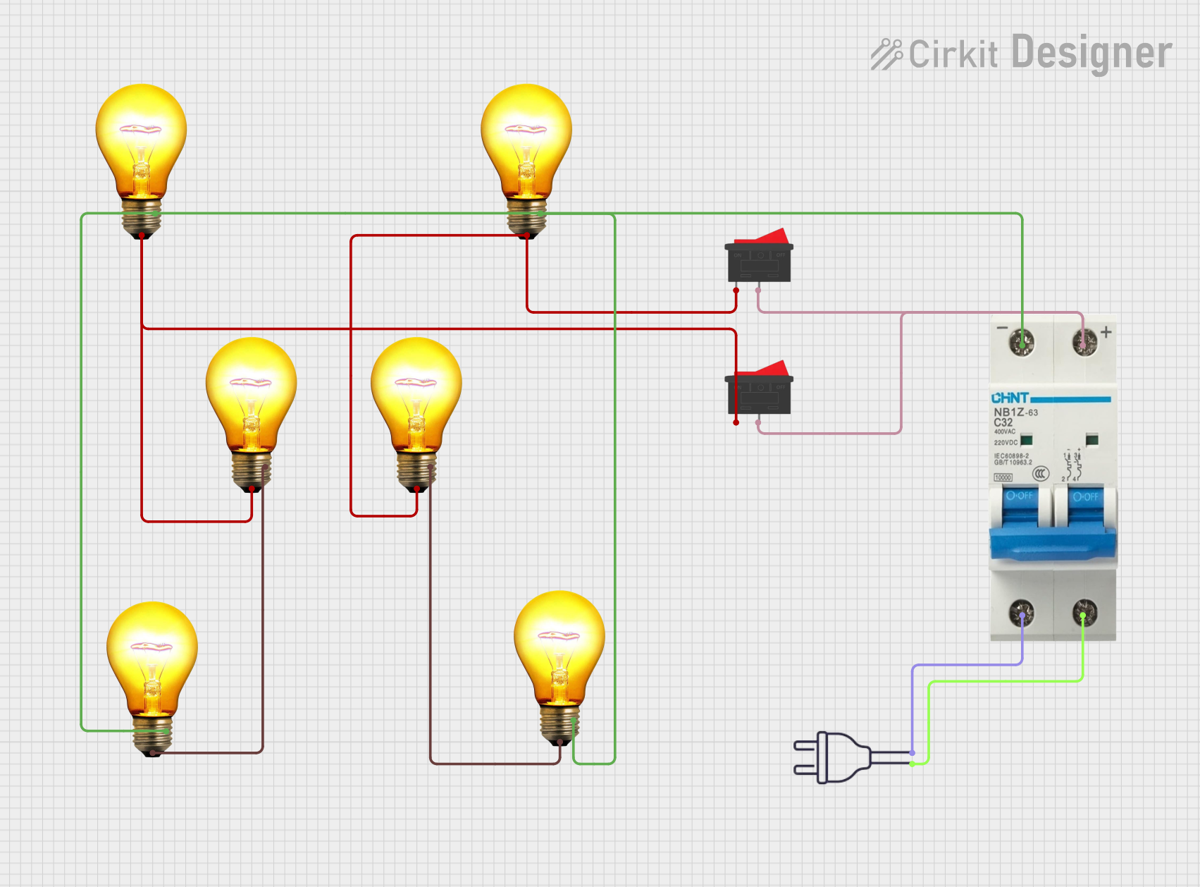

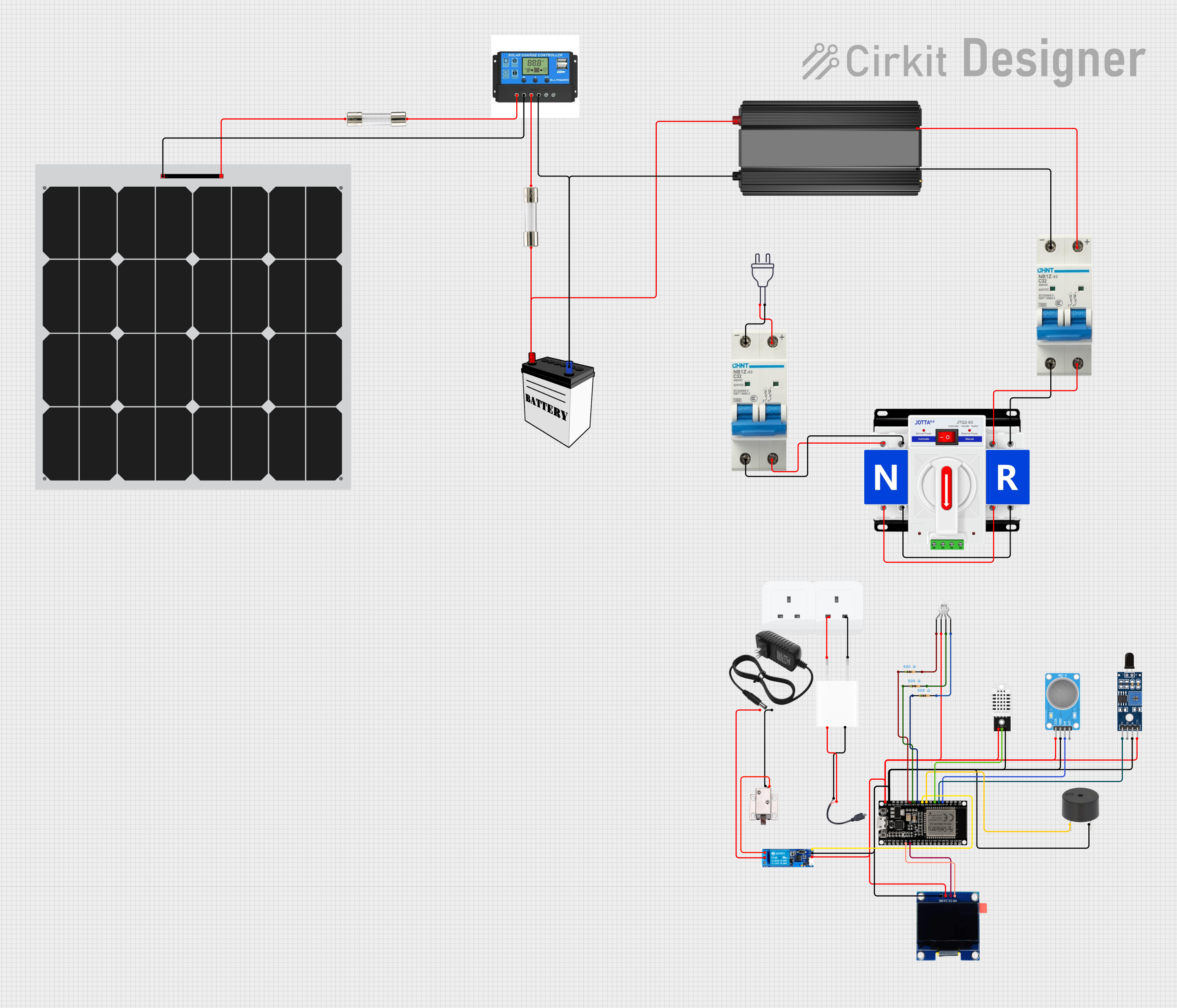

Explore Projects Built with 2P Breaker
Technical Specifications
Below are the key technical details of a typical 2P breaker:
| Parameter | Specification |
|---|---|
| Rated Voltage | 240V AC |
| Rated Current | 10A, 20A, 30A, 40A, 50A (varies by model) |
| Number of Poles | 2 |
| Interrupting Capacity | 10kA at 240V AC (varies by model) |
| Trip Mechanism | Thermal-magnetic |
| Mounting Type | DIN rail or panel mount |
| Operating Temperature | -20°C to 60°C |
| Compliance Standards | IEC 60898, UL 489, or equivalent |
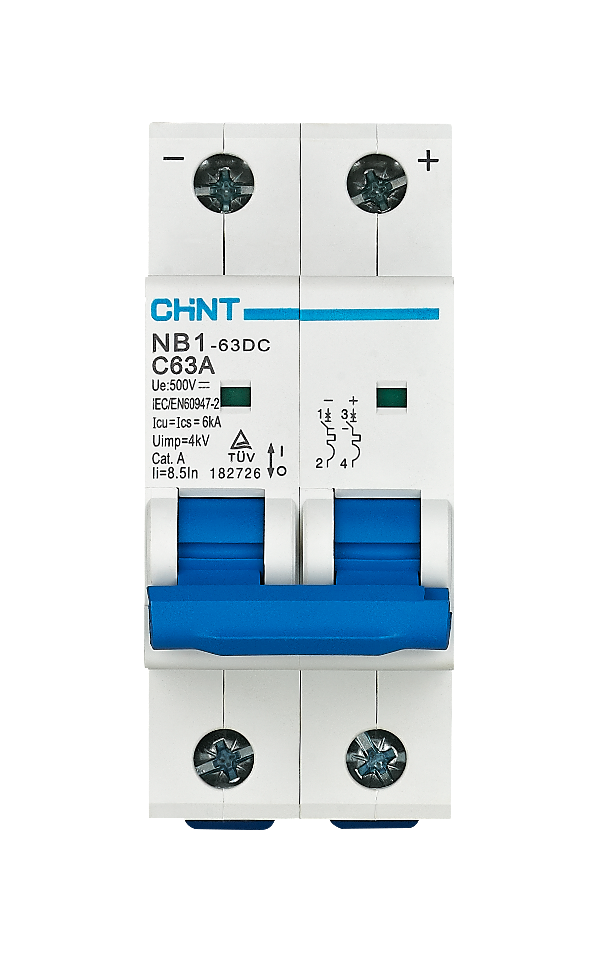
Pin Configuration and Descriptions
The 2P breaker does not have traditional "pins" like electronic components but instead features terminals for connecting wires. Below is a description of the terminals:
| Terminal | Description |
|---|---|
| Line 1 (L1) | Connects to the first phase of the incoming power supply. |
| Line 2 (L2) | Connects to the second phase of the incoming power supply. |
| Load 1 | Connects to the first phase of the outgoing circuit (protected load). |
| Load 2 | Connects to the second phase of the outgoing circuit (protected load). |
Usage Instructions
How to Use the 2P Breaker in a Circuit
- Determine the Load Requirements: Ensure the breaker’s rated current matches the load requirements of your circuit. For example, use a 20A breaker for a circuit with a maximum load of 20A.
- Turn Off Power: Before installation, disconnect power to the circuit to avoid electrical shock.
- Connect the Wires:
- Connect the incoming power supply wires to the Line 1 (L1) and Line 2 (L2) terminals.
- Connect the outgoing load wires to the Load 1 and Load 2 terminals.
- Secure the Breaker: Mount the breaker onto a DIN rail or panel as per the installation requirements.
- Test the Circuit: After installation, turn on the power and test the breaker by manually tripping it to ensure it disconnects the circuit properly.
Important Considerations and Best Practices
- Select the Correct Breaker: Always choose a breaker with the appropriate voltage and current ratings for your application.
- Avoid Overloading: Do not exceed the breaker's rated current, as this can cause nuisance tripping or damage.
- Regular Maintenance: Periodically inspect the breaker for signs of wear, corrosion, or damage.
- Proper Wiring: Ensure all connections are secure and that the wire gauge matches the current rating of the breaker.
Example: Connecting a 2P Breaker to an Arduino-Controlled Circuit
While a 2P breaker is not directly interfaced with an Arduino, it can be used to protect circuits controlled by an Arduino. For example, if an Arduino is used to control a high-power motor, the 2P breaker can be installed between the power source and the motor to provide overload protection.
// Example Arduino code to control a motor via a relay
// Ensure the motor circuit is protected by a 2P breaker

const int relayPin = 7; // Pin connected to the relay module

void setup() {
  pinMode(relayPin, OUTPUT); // Set relay pin as output
  digitalWrite(relayPin, LOW); // Ensure relay is off at startup
}

void loop() {
  // Turn on the motor
  digitalWrite(relayPin, HIGH); // Activate relay to power the motor
  delay(5000); // Run motor for 5 seconds

  // Turn off the motor
  digitalWrite(relayPin, LOW); // Deactivate relay to cut power
  delay(5000); // Wait for 5 seconds before restarting
}
Note: The 2P breaker should be installed on the power supply line to the motor, not directly in the Arduino circuit.
Troubleshooting and FAQs
Common Issues and Solutions
| Issue | Possible Cause | Solution |
|---|---|---|
| Breaker trips frequently | Overloaded circuit | Reduce the load or use a breaker with a higher current rating (if appropriate). |
| Breaker does not trip during a fault | Faulty breaker or incorrect installation | Inspect the breaker and ensure proper wiring. Replace if necessary. |
| Breaker cannot be reset | Internal damage or persistent fault | Check for short circuits or replace the breaker if damaged. |
| Breaker feels hot during operation | Loose connections or high ambient temperature | Tighten connections and ensure proper ventilation. |
FAQs
Can I use a 2P breaker for single-phase circuits? Yes, a 2P breaker can be used for single-phase circuits by connecting only one pole, but this is not recommended unless specified by the manufacturer.
What is the difference between a 2P breaker and a 1P breaker? A 2P breaker protects two-phase circuits (e.g., 240V) and disconnects both phases simultaneously, while a 1P breaker protects single-phase circuits (e.g., 120V).
How do I know if my breaker is faulty? If the breaker trips without a load, cannot be reset, or shows visible damage, it may be faulty and should be replaced.
Can I install a 2P breaker myself? Installation should be performed by a qualified electrician to ensure safety and compliance with local electrical codes.