Cirkit Designer Logo
Cirkit Designer
Your all-in-one circuit design IDE
Home / 
Component Documentation

How to Use ESP32-WROOM: Examples, Pinouts, and Specs

Image of ESP32-WROOM
Cirkit Designer LogoDesign with ESP32-WROOM in Cirkit Designer

Introduction

The ESP32-WROOM, manufactured by Espressif Systems, is a versatile and powerful microcontroller module designed for Internet of Things (IoT) applications. It features integrated Wi-Fi and Bluetooth capabilities, a dual-core processor, and a wide range of GPIO pins, making it suitable for a variety of embedded systems. The module is compact, energy-efficient, and supports multiple communication protocols, making it a popular choice for developers and hobbyists alike.

Explore Projects Built with ESP32-WROOM

Use Cirkit Designer to design, explore, and prototype these projects online. Some projects support real-time simulation. Click "Open Project" to start designing instantly!
ESP32-Based GPS Tracker with SD Card Logging and Barometric Sensor
Image of gps projekt circuit: A project utilizing ESP32-WROOM in a practical application
This circuit features an ESP32 Wroom Dev Kit as the main microcontroller, interfaced with an MPL3115A2 sensor for pressure and temperature readings, and a Neo 6M GPS module for location tracking. The ESP32 is also connected to an SD card reader for data logging purposes. A voltage regulator is used to step down the USB power supply to 3.3V, which powers the ESP32, the sensor, and the SD card reader.
Cirkit Designer LogoOpen Project in Cirkit Designer
ESP32-Based Multi-Sensor Health Monitoring System with Bluetooth Connectivity
Image of circuit diagram: A project utilizing ESP32-WROOM in a practical application
This circuit features an ESP32-WROOM-32UE microcontroller as the central processing unit, interfacing with a variety of sensors and modules. It includes a MAX30100 pulse oximeter and heart-rate sensor, an MLX90614 infrared thermometer, an HC-05 Bluetooth module for wireless communication, and a Neo 6M GPS module for location tracking. All components are powered by a common voltage supply and are connected to specific GPIO pins on the ESP32 for data exchange, with the sensors using I2C communication and the modules using UART.
Cirkit Designer LogoOpen Project in Cirkit Designer
ESP32-Controlled WS2812 RGB LED Strip
Image of LED: A project utilizing ESP32-WROOM in a practical application
This circuit features an ESP32 Wroom Dev Kit microcontroller connected to a WS2812 RGB LED strip. The ESP32's GPIO 4 is used to send data to the LED strip's data input (DIN), while both the ESP32 and the LED strip share a common ground. A separate Vcc power source is connected to the 5V pin of the LED strip to provide power.
Cirkit Designer LogoOpen Project in Cirkit Designer
ESP32-Controlled WS2812 RGB LED Strip Lighting System
Image of WLED Addressable LED: A project utilizing ESP32-WROOM in a practical application
This circuit features an ESP32 Wroom microcontroller connected to a WS2812 RGB LED strip for controlling the LED lighting. The ESP32 is powered by a 5V supply from a breadboard power module, which also provides the 5V needed by the LED strip. The ground connections are shared among all components to complete the circuit, and the ESP32's GPIO13 is used to send data to the LED strip's data input (DIN).
Cirkit Designer LogoOpen Project in Cirkit Designer

Explore Projects Built with ESP32-WROOM

Use Cirkit Designer to design, explore, and prototype these projects online. Some projects support real-time simulation. Click "Open Project" to start designing instantly!
Image of gps projekt circuit: A project utilizing ESP32-WROOM in a practical application
ESP32-Based GPS Tracker with SD Card Logging and Barometric Sensor
This circuit features an ESP32 Wroom Dev Kit as the main microcontroller, interfaced with an MPL3115A2 sensor for pressure and temperature readings, and a Neo 6M GPS module for location tracking. The ESP32 is also connected to an SD card reader for data logging purposes. A voltage regulator is used to step down the USB power supply to 3.3V, which powers the ESP32, the sensor, and the SD card reader.
Cirkit Designer LogoOpen Project in Cirkit Designer
Image of circuit diagram: A project utilizing ESP32-WROOM in a practical application
ESP32-Based Multi-Sensor Health Monitoring System with Bluetooth Connectivity
This circuit features an ESP32-WROOM-32UE microcontroller as the central processing unit, interfacing with a variety of sensors and modules. It includes a MAX30100 pulse oximeter and heart-rate sensor, an MLX90614 infrared thermometer, an HC-05 Bluetooth module for wireless communication, and a Neo 6M GPS module for location tracking. All components are powered by a common voltage supply and are connected to specific GPIO pins on the ESP32 for data exchange, with the sensors using I2C communication and the modules using UART.
Cirkit Designer LogoOpen Project in Cirkit Designer
Image of LED: A project utilizing ESP32-WROOM in a practical application
ESP32-Controlled WS2812 RGB LED Strip
This circuit features an ESP32 Wroom Dev Kit microcontroller connected to a WS2812 RGB LED strip. The ESP32's GPIO 4 is used to send data to the LED strip's data input (DIN), while both the ESP32 and the LED strip share a common ground. A separate Vcc power source is connected to the 5V pin of the LED strip to provide power.
Cirkit Designer LogoOpen Project in Cirkit Designer
Image of WLED Addressable LED: A project utilizing ESP32-WROOM in a practical application
ESP32-Controlled WS2812 RGB LED Strip Lighting System
This circuit features an ESP32 Wroom microcontroller connected to a WS2812 RGB LED strip for controlling the LED lighting. The ESP32 is powered by a 5V supply from a breadboard power module, which also provides the 5V needed by the LED strip. The ground connections are shared among all components to complete the circuit, and the ESP32's GPIO13 is used to send data to the LED strip's data input (DIN).
Cirkit Designer LogoOpen Project in Cirkit Designer

Common Applications and Use Cases

  • IoT devices and smart home automation
  • Wireless sensor networks
  • Industrial automation and control systems
  • Wearable devices
  • Robotics and drones
  • Prototyping and educational projects

Technical Specifications

Key Technical Details

Parameter Value
Manufacturer Espressif Systems
Part ID ESP32-WROOM
Processor Dual-core Xtensa® 32-bit LX6 CPU
Clock Speed Up to 240 MHz
Flash Memory 4 MB (default, expandable in variants)
SRAM 520 KB
Wireless Connectivity Wi-Fi 802.11 b/g/n, Bluetooth v4.2 BR/EDR
Operating Voltage 3.0V to 3.6V
GPIO Pins 34 (multipurpose)
Communication Protocols UART, SPI, I2C, I2S, PWM, ADC, DAC
ADC Channels 18 (12-bit resolution)
Operating Temperature -40°C to +85°C
Dimensions 18 mm x 25.5 mm x 3.1 mm

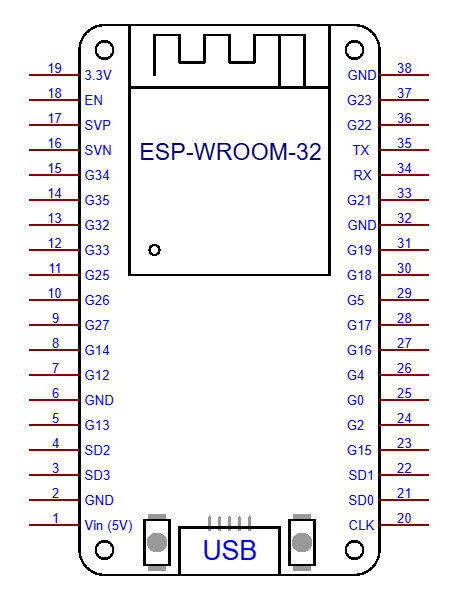
Pin Configuration and Descriptions

The ESP32-WROOM module has 38 pins. Below is a summary of the key pins and their functions:

Pin Number Pin Name Function Description
1 EN Enable pin (active high)
2 IO0 GPIO0, used for boot mode selection
3 IO1 (TX0) GPIO1, UART0 TX
4 IO3 (RX0) GPIO3, UART0 RX
5 IO4 GPIO4, general-purpose I/O
6 IO5 GPIO5, general-purpose I/O
7 IO12 GPIO12, ADC2 channel 5
8 IO13 GPIO13, ADC2 channel 4
9 IO14 GPIO14, ADC2 channel 6
10 IO15 GPIO15, ADC2 channel 3
11 IO16 GPIO16, general-purpose I/O
12 IO17 GPIO17, general-purpose I/O
13 GND Ground
14 3V3 3.3V power supply

Note: Not all GPIO pins support all functions simultaneously. Refer to the ESP32 datasheet for detailed pin multiplexing information.

Usage Instructions

How to Use the ESP32-WROOM in a Circuit

  1. Power Supply: Provide a stable 3.3V power supply to the module. Avoid exceeding 3.6V to prevent damage.
  2. Boot Mode: Connect GPIO0 to GND during power-up to enter bootloader mode for programming.
  3. Communication: Use UART, SPI, or I2C for interfacing with external devices. Ensure proper pull-up resistors for I2C lines.
  4. Programming: The ESP32-WROOM can be programmed using the Arduino IDE, Espressif's ESP-IDF, or other compatible tools.
  5. Antenna Placement: Ensure the onboard antenna has sufficient clearance from metallic objects to avoid signal interference.

Important Considerations and Best Practices

  • Use decoupling capacitors (e.g., 0.1 µF) near the power pins to reduce noise.
  • Avoid using GPIO pins 6-11, as they are connected to the module's internal flash memory.
  • For ADC applications, note that ADC2 channels cannot be used when Wi-Fi is active.
  • Use level shifters if interfacing with 5V logic devices, as the ESP32 operates at 3.3V logic levels.

Example Code for Arduino UNO Integration

Below is an example of using the ESP32-WROOM with the Arduino IDE to blink an LED connected to GPIO2:

// Example: Blink an LED using ESP32-WROOM
// Connect an LED to GPIO2 with a current-limiting resistor

#define LED_PIN 2  // GPIO2 is connected to the LED

void setup() {
  pinMode(LED_PIN, OUTPUT);  // Set GPIO2 as an output pin
}

void loop() {
  digitalWrite(LED_PIN, HIGH);  // Turn the LED on
  delay(1000);                  // Wait for 1 second
  digitalWrite(LED_PIN, LOW);   // Turn the LED off
  delay(1000);                  // Wait for 1 second
}

Tip: Install the ESP32 board package in the Arduino IDE before uploading the code. Go to File > Preferences, add the ESP32 board URL, and install the package via the Board Manager.

Troubleshooting and FAQs

Common Issues and Solutions

  1. ESP32-WROOM Not Detected by PC:

    • Ensure the correct USB-to-serial driver is installed (e.g., CP210x or CH340).
    • Check the USB cable for data transfer capability (some cables are power-only).
  2. Wi-Fi Connection Fails:

    • Verify the SSID and password in your code.
    • Ensure the router is within range and supports 2.4 GHz Wi-Fi.
  3. Module Overheats:

    • Check for proper power supply voltage (3.3V).
    • Avoid short circuits on GPIO pins.
  4. Boot Mode Issues:

    • Ensure GPIO0 is connected to GND during bootloader mode.
    • Verify the EN pin is pulled high.

FAQs

Q: Can the ESP32-WROOM operate on 5V?
A: No, the ESP32-WROOM operates at 3.3V. Use a voltage regulator or level shifter for 5V systems.

Q: How do I reset the module?
A: Pull the EN pin low momentarily to reset the module.

Q: Can I use Bluetooth and Wi-Fi simultaneously?
A: Yes, the ESP32 supports simultaneous use of Bluetooth and Wi-Fi, but performance may vary depending on the application.

Q: What is the maximum range of the Wi-Fi?
A: The Wi-Fi range is approximately 50 meters indoors and 200 meters outdoors, depending on environmental factors.

For more detailed information, refer to the official ESP32-WROOM datasheet and Espressif's documentation.