
How to Use Adafruit Airlift Bitsy Add-On: Examples, Pinouts, and Specs
 Design with Adafruit Airlift Bitsy Add-On in Cirkit Designer
Introduction
The Adafruit Airlift Bitsy Add-On (Manufacturer Part ID: 4363) is a Wi-Fi co-processor designed to provide seamless wireless connectivity to the Adafruit ItsyBitsy microcontroller series. Powered by the Espressif ESP32 chip, this add-on simplifies the integration of Wi-Fi functionality into IoT projects by offloading the networking stack from the main microcontroller. It is ideal for applications requiring reliable wireless communication, such as smart home devices, data logging, and remote monitoring systems.
Explore Projects Built with Adafruit Airlift Bitsy Add-On
 Open Project in Cirkit Designer
 Open Project in Cirkit Designer
 Open Project in Cirkit Designer
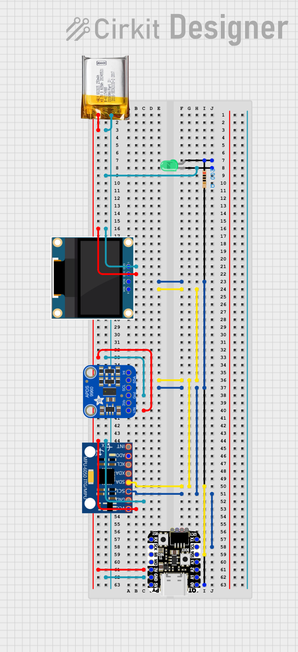 Open Project in Cirkit Designer
Explore Projects Built with Adafruit Airlift Bitsy Add-On
Open Project in Cirkit DesignerOpen Project in Cirkit DesignerOpen Project in Cirkit DesignerOpen Project in Cirkit DesignerCommon Applications and Use Cases
- IoT (Internet of Things) devices
- Wireless data logging and monitoring
- Smart home automation
- Remote control systems
- Cloud-based applications and services
Technical Specifications
The Adafruit Airlift Bitsy Add-On is designed to work seamlessly with the Adafruit ItsyBitsy microcontroller series. Below are the key technical details:
Key Specifications
| Parameter | Value |
|---|---|
| Wi-Fi Chip | Espressif ESP32 |
| Operating Voltage | 3.3V |
| Communication | SPI |
| Power Consumption | ~80mA (typical during operation) |
| Dimensions | 36mm x 18mm x 3mm |
| Compatibility | Adafruit ItsyBitsy (3V or 5V logic) |
Pin Configuration and Descriptions
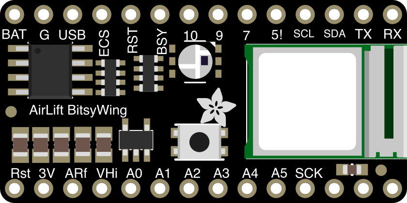
The Airlift Bitsy Add-On connects directly to the Adafruit ItsyBitsy microcontroller via its pin headers. Below is the pin configuration:
| Pin Name | Description |
|---|---|
| 3V | Power input (3.3V) |
| GND | Ground connection |
| SCK | SPI Clock |
| MOSI | SPI Master Out, Slave In |
| MISO | SPI Master In, Slave Out |
| CS | Chip Select for SPI communication |
| RST | Reset pin for the ESP32 |
| BUSY | Status pin indicating Wi-Fi module activity |
| GPIO0 | Used for firmware updates or boot mode selection |
Usage Instructions
How to Use the Component in a Circuit
Hardware Setup:
- Align the Airlift Bitsy Add-On with the Adafruit ItsyBitsy microcontroller's pin headers.
- Ensure proper alignment of the 3V, GND, and SPI pins.
- Solder the headers for a secure connection or use a breadboard for prototyping.
Power Requirements:
- The add-on operates at 3.3V. Ensure the ItsyBitsy microcontroller provides sufficient power.
Software Setup:
- Install the Adafruit WiFiNINA library in the Arduino IDE. This library provides the necessary functions to communicate with the Airlift module.
- Configure the SPI pins in your code to match the ItsyBitsy pinout.
Example Code for Arduino UNO
Below is an example sketch to connect the Airlift Bitsy Add-On to a Wi-Fi network:
#include <SPI.h>
#include <WiFiNINA.h>

// Define SPI pins for the Airlift Bitsy Add-On
#define SPIWIFI       SPI
#define SPIWIFI_SS    10  // Chip Select pin
#define SPIWIFI_ACK   9   // BUSY pin
#define ESP32_RESETN  6   // Reset pin
#define ESP32_GPIO0   -1  // Not used in this example

// Wi-Fi credentials
const char* ssid = "YourNetworkSSID";
const char* password = "YourNetworkPassword";

void setup() {
  Serial.begin(115200);
  while (!Serial); // Wait for Serial Monitor to open

  // Initialize the Wi-Fi module
  WiFi.setPins(SPIWIFI_SS, ESP32_GPIO0, ESP32_RESETN, SPIWIFI_ACK);
  if (WiFi.status() == WL_NO_MODULE) {
    Serial.println("WiFi module not found. Check your wiring.");
    while (true);
  }

  // Attempt to connect to Wi-Fi
  Serial.print("Connecting to Wi-Fi...");
  while (WiFi.begin(ssid, password) != WL_CONNECTED) {
    delay(1000);
    Serial.print(".");
  }
  Serial.println("\nConnected to Wi-Fi!");
}

void loop() {
  // Print the IP address
  Serial.print("IP Address: ");
  Serial.println(WiFi.localIP());
  delay(5000);
}
Important Considerations and Best Practices
- Ensure the ItsyBitsy microcontroller is configured to operate at 3.3V logic levels.
- Avoid powering the Airlift Bitsy Add-On directly from a 5V source.
- Use a stable power supply to prevent unexpected resets or connection drops.
- Keep the firmware of the ESP32 chip updated for optimal performance and security.
Troubleshooting and FAQs
Common Issues and Solutions
Wi-Fi Module Not Detected:
- Ensure the Airlift Bitsy Add-On is properly connected to the ItsyBitsy microcontroller.
- Verify the SPI pin configuration in your code matches the hardware setup.
Unable to Connect to Wi-Fi:
- Double-check the SSID and password for your Wi-Fi network.
- Ensure the Wi-Fi network is operating on a 2.4GHz band (the ESP32 does not support 5GHz).
Frequent Disconnections:
- Check for power supply stability. Use a decoupling capacitor if necessary.
- Reduce interference from nearby electronic devices.
Firmware Update Issues:
- Ensure the GPIO0 pin is correctly configured for firmware updates.
- Use the latest version of the Adafruit WiFiNINA library.
FAQs
Q: Can I use the Airlift Bitsy Add-On with microcontrollers other than ItsyBitsy?
A: Yes, the add-on can work with other microcontrollers that support SPI communication, but additional wiring may be required.
Q: Does the Airlift Bitsy Add-On support Bluetooth?
A: No, the Airlift Bitsy Add-On is designed specifically for Wi-Fi connectivity.
Q: How do I update the firmware on the ESP32 chip?
A: Use the Adafruit firmware update tool and connect the GPIO0 pin to enable boot mode. Follow the instructions provided in the Adafruit documentation.
Q: Can I use this module for secure HTTPS communication?
A: Yes, the Airlift Bitsy Add-On supports secure HTTPS connections using the WiFiNINA library.
By following this documentation, you can effectively integrate the Adafruit Airlift Bitsy Add-On into your IoT projects and leverage its powerful Wi-Fi capabilities.