How to Use TIMER: Examples, Pinouts, and Specs
Introduction
A timer is an electronic device designed to count down or count up time intervals. It is commonly used in circuits to control the timing of operations or events. Timers are integral to a wide range of applications, from simple blinking LEDs to complex industrial automation systems. They can be implemented as standalone integrated circuits (ICs) or as part of microcontroller functionality.
Explore Projects Built with TIMER
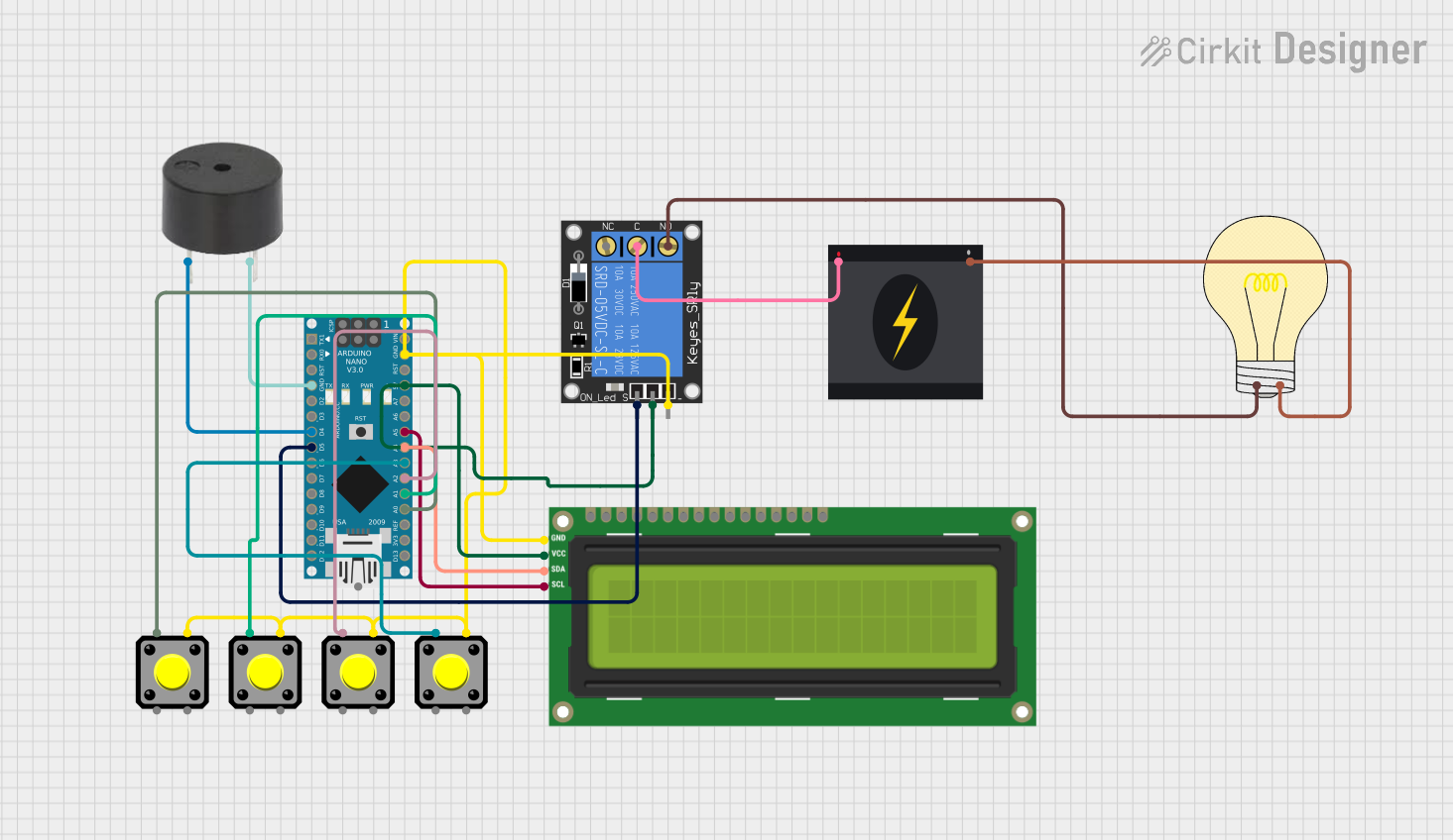
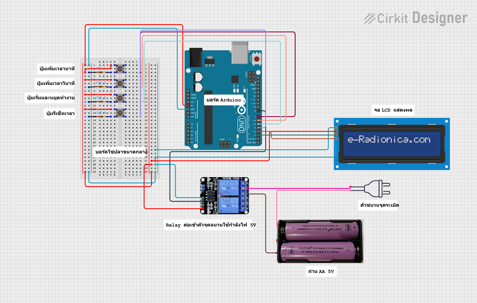

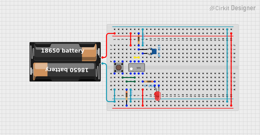
Explore Projects Built with TIMER
Common Applications and Use Cases
- Generating precise time delays in circuits
- Pulse Width Modulation (PWM) for motor control or LED dimming
- Event scheduling in embedded systems
- Frequency generation and measurement
- Debouncing mechanical switches
- Real-time clock (RTC) functionality in digital systems
Technical Specifications
Timers come in various forms, such as standalone ICs (e.g., 555 Timer) or built-in modules in microcontrollers. Below are the general technical specifications for a common standalone timer IC, the 555 Timer:
Key Technical Details
- Operating Voltage: 4.5V to 15V
- Output Current: Up to 200mA
- Frequency Range: Up to 500kHz
- Timing Accuracy: ±1% (depending on external components)
- Operating Temperature: -40°C to 125°C
- Modes of Operation: Monostable, Astable, and Bistable
Pin Configuration and Descriptions
The 555 Timer IC is an 8-pin device. Below is the pinout and description:
| Pin Number | Pin Name | Description |
|---|---|---|
| 1 | GND | Ground pin, connected to the negative terminal of the power supply. |
| 2 | TRIG | Trigger input, starts the timing interval when voltage drops below 1/3 Vcc. |
| 3 | OUT | Output pin, provides the timer's output signal. |
| 4 | RESET | Resets the timer when pulled low. |
| 5 | CTRL | Control voltage, used to adjust the threshold voltage (optional). |
| 6 | THR | Threshold input, ends the timing interval when voltage exceeds 2/3 Vcc. |
| 7 | DISCH | Discharge pin, used to discharge the timing capacitor. |
| 8 | VCC | Positive power supply pin. |
Usage Instructions
How to Use the Timer in a Circuit
The 555 Timer can operate in three primary modes: Monostable, Astable, and Bistable. Below is an example of using the timer in Astable Mode to generate a square wave:
- Connect the Power Supply: Connect Pin 8 (VCC) to the positive terminal and Pin 1 (GND) to the negative terminal of the power supply.
- Configure External Components:
- Connect a resistor (R1) between Pin 8 (VCC) and Pin 7 (DISCH).
- Connect another resistor (R2) between Pin 7 (DISCH) and Pin 6 (THR).
- Connect a capacitor (C1) between Pin 6 (THR) and Pin 1 (GND).
- Connect the Output: Use Pin 3 (OUT) to drive the desired load (e.g., an LED or a microcontroller input).
- Optional Control: If needed, connect a voltage to Pin 5 (CTRL) to adjust the timing interval.
The output frequency (f) and duty cycle (D) can be calculated as:
- Frequency: ( f = \frac{1.44}{(R1 + 2R2) \cdot C1} )
- Duty Cycle: ( D = \frac{R1 + R2}{R1 + 2R2} )
Example: Using a Timer with Arduino UNO
The 555 Timer can be used alongside an Arduino UNO to generate a PWM signal. Below is an example Arduino code to read the timer's output:
// Define the pin connected to the 555 Timer's output
const int timerOutputPin = 2;

void setup() {
  pinMode(timerOutputPin, INPUT); // Set the timer output pin as input
  Serial.begin(9600);            // Initialize serial communication
}

void loop() {
  int timerState = digitalRead(timerOutputPin); // Read the timer's output state
  Serial.print("Timer Output: ");
  Serial.println(timerState); // Print the timer's output state to the Serial Monitor
  delay(100);                 // Add a small delay for readability
}
Important Considerations and Best Practices
- Use decoupling capacitors (e.g., 0.1µF) near the power supply pins to reduce noise.
- Ensure the resistor and capacitor values are within the recommended range for stable operation.
- Avoid leaving unused pins floating; connect them to appropriate voltage levels as specified in the datasheet.
- For precise timing, use high-quality resistors and capacitors with low tolerance values.
Troubleshooting and FAQs
Common Issues and Solutions
Timer Output Not Working:
- Cause: Incorrect wiring or loose connections.
- Solution: Double-check the circuit connections and ensure all components are properly soldered or inserted.
Unstable Output Signal:
- Cause: Noise or improper decoupling.
- Solution: Add a 0.1µF decoupling capacitor near the VCC pin.
Incorrect Timing Interval:
- Cause: Incorrect resistor or capacitor values.
- Solution: Verify the resistor and capacitor values and recalculate the timing interval.
Output Signal Too Weak:
- Cause: Exceeding the output current limit.
- Solution: Use a transistor or MOSFET to amplify the output signal if driving a high-current load.
FAQs
Q1: Can the 555 Timer operate at 3.3V?
A1: Yes, some low-power variants of the 555 Timer can operate at 3.3V. Check the datasheet for compatibility.
Q2: How do I calculate the timing interval in Monostable Mode?
A2: The timing interval is given by ( T = 1.1 \cdot R \cdot C ), where R is the resistor value and C is the capacitor value.
Q3: Can I use the 555 Timer for audio frequency generation?
A3: Yes, the 555 Timer can generate audio frequencies, but its waveform may require filtering for high-quality audio applications.
Q4: What is the maximum frequency the 555 Timer can generate?
A4: The maximum frequency depends on the specific 555 Timer variant but is typically around 500kHz for standard models.
By following this documentation, you can effectively integrate a timer into your electronic projects and troubleshoot common issues with ease.