
How to Use Push button: Examples, Pinouts, and Specs
 Design with Push button in Cirkit Designer
Introduction
A push button is a momentary switch that completes a circuit when pressed and breaks the circuit when released. It is widely used in electronic devices for user input, such as turning devices on/off, resetting systems, or triggering specific actions. Push buttons are simple yet versatile components that can be found in a variety of applications, including consumer electronics, industrial machinery, and DIY electronics projects.
Explore Projects Built with Push button
 Open Project in Cirkit Designer
 Open Project in Cirkit Designer
 Open Project in Cirkit Designer
 Open Project in Cirkit Designer
Explore Projects Built with Push button
Open Project in Cirkit DesignerOpen Project in Cirkit DesignerOpen Project in Cirkit DesignerOpen Project in Cirkit DesignerTechnical Specifications
- Type: Momentary switch
- Contact Configuration: Normally Open (NO) or Normally Closed (NC)
- Operating Voltage: Typically 3.3V to 12V (depends on the circuit design)
- Current Rating: 50mA to 500mA (varies by model)
- Contact Resistance: < 50 mΩ
- Insulation Resistance: > 100 MΩ
- Debounce Time: ~5ms to 20ms (mechanical property)
- Lifespan: 100,000 to 1,000,000 actuations (varies by model)
Pin Configuration and Descriptions
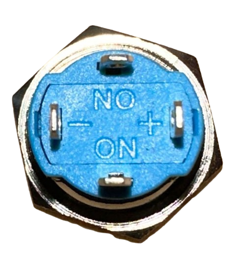
Push buttons typically have two or four pins. Below is a description of the pin configuration:
For a 2-pin push button:
| Pin Number | Description |
|---|---|
| 1 | One terminal of the switch |
| 2 | The other terminal of the switch |
For a 4-pin push button:
| Pin Number | Description |
|---|---|
| 1 | Connected internally to Pin 2 |
| 2 | Connected internally to Pin 1 |
| 3 | Connected internally to Pin 4 |
| 4 | Connected internally to Pin 3 |
Note: In a 4-pin push button, pins 1 and 2 are internally connected, and pins 3 and 4 are internally connected. This allows for easier placement on a breadboard.
Usage Instructions
How to Use the Push Button in a Circuit
Connect the Push Button:
- For a 2-pin push button, connect one pin to the input signal (e.g., microcontroller pin) and the other to ground.
- For a 4-pin push button, connect one pair of internally connected pins to the input signal and the other pair to ground.
Use a Pull-Down Resistor:
- To ensure a stable signal, connect a pull-down resistor (typically 10kΩ) between the input pin and ground. This prevents floating signals when the button is not pressed.
Debouncing:
- Mechanical push buttons can produce noise or "bouncing" when pressed. Use a software debounce routine or a hardware debounce circuit (e.g., an RC filter) to eliminate this issue.
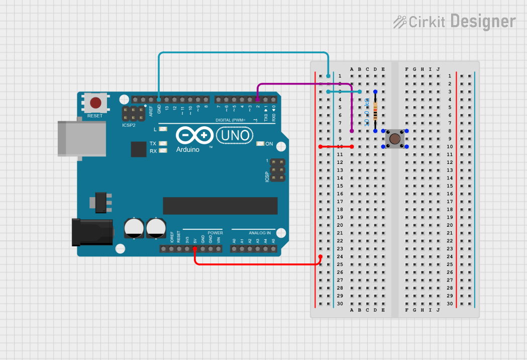
Example Circuit with Arduino UNO
Below is an example of how to connect a push button to an Arduino UNO and read its state:
Circuit Connections:
- Connect one terminal of the push button to digital pin 2 on the Arduino.
- Connect the other terminal to ground.
- Add a 10kΩ pull-down resistor between digital pin 2 and ground.
Arduino Code:
// Define the pin connected to the push button
const int buttonPin = 2;

// Variable to store the button state
int buttonState = 0;

void setup() {
  // Set the button pin as input
  pinMode(buttonPin, INPUT);

  // Initialize serial communication for debugging
  Serial.begin(9600);
}

void loop() {
  // Read the state of the push button
  buttonState = digitalRead(buttonPin);

  // Print the button state to the Serial Monitor
  if (buttonState == HIGH) {
    Serial.println("Button Pressed");
  } else {
    Serial.println("Button Released");
  }

  // Add a small delay to avoid spamming the Serial Monitor
  delay(100);
}
Important Considerations and Best Practices
- Always use a pull-up or pull-down resistor to avoid floating input signals.
- If using the push button in a high-current circuit, ensure it is rated for the required current.
- For long-term reliability, avoid exposing the push button to excessive moisture or dust.
Troubleshooting and FAQs
Common Issues
Button Not Responding:
- Cause: Loose connections or incorrect wiring.
- Solution: Double-check the wiring and ensure all connections are secure.
Button Produces Erratic Behavior:
- Cause: Signal bouncing due to mechanical properties.
- Solution: Implement software or hardware debouncing.
Button Works Intermittently:
- Cause: Faulty button or worn-out contacts.
- Solution: Replace the push button with a new one.
Arduino Not Detecting Button Press:
- Cause: Missing pull-down resistor or incorrect pin configuration.
- Solution: Add a pull-down resistor and verify the pin setup in the code.
FAQs
Q1: Can I use a push button without a pull-down resistor?
A1: While it is possible, it is not recommended. Without a pull-down resistor, the input pin may float, leading to unreliable behavior.
Q2: How do I debounce a push button in software?
A2: You can use a delay after detecting a button press or implement a debounce algorithm that checks for consistent readings over a short period.
Q3: Can I use a push button with a 5V relay?
A3: Yes, but ensure the push button is rated for the current required to activate the relay. If not, use the push button to control a transistor or MOSFET that drives the relay.
Q4: What is the difference between Normally Open (NO) and Normally Closed (NC) push buttons?
A4: An NO push button completes the circuit when pressed, while an NC push button breaks the circuit when pressed.