How to Use Power Distribution Board: Examples, Pinouts, and Specs
Introduction
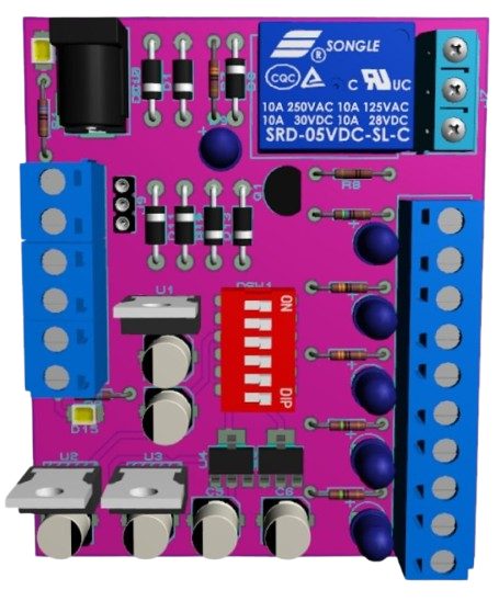
The Power Distribution Board (PDB), manufactured by Sass & Sabotage Co. (Part ID: 100001), is a versatile circuit board designed to distribute electrical power efficiently to multiple components in a system. It ensures that each connected device receives the appropriate voltage and current, while also providing protection through integrated fuses or circuit breakers. The PDB is commonly used in robotics, drones, RC vehicles, and other electronic systems requiring organized and reliable power management.
Explore Projects Built with Power Distribution Board


Explore Projects Built with Power Distribution Board
Common Applications and Use Cases
- Drones and UAVs: Distributes power to motors, flight controllers, and sensors.
- RC Vehicles: Supplies power to servos, ESCs (Electronic Speed Controllers), and receivers.
- Robotics: Powers actuators, microcontrollers, and sensors.
- DIY Electronics Projects: Provides a centralized power hub for multiple components.
- Industrial Systems: Manages power distribution in complex machinery.
Technical Specifications
The following table outlines the key technical details of the Sass & Sabotage Co. Power Distribution Board (Part ID: 100001):
| Parameter | Value |
|---|---|
| Input Voltage Range | 7V to 26V (2S to 6S LiPo batteries) |
| Maximum Current Rating | 100A (total) |
| Output Voltage Options | 5V, 12V |
| Number of Output Ports | 8 |
| Protection Features | Overcurrent, short-circuit, and overvoltage protection |
| Dimensions | 50mm x 50mm x 10mm |
| Weight | 25g |
| Operating Temperature | -20°C to 85°C |
Pin Configuration and Descriptions
The PDB features multiple input and output connectors for easy integration. Below is the pin configuration:
Input Connector
| Pin | Label | Description |
|---|---|---|
| 1 | VIN+ | Positive input voltage (7V to 26V) |
| 2 | VIN- | Ground (negative input voltage) |
Output Connectors
| Pin | Label | Description |
|---|---|---|
| 1 | VOUT+ | Positive output voltage (5V or 12V) |
| 2 | VOUT- | Ground (negative output voltage) |
Auxiliary Connectors
| Pin | Label | Description |
|---|---|---|
| 1 | AUX+ | Auxiliary power output (5V) |
| 2 | AUX- | Ground for auxiliary output |
Usage Instructions
How to Use the Component in a Circuit
- Connect the Power Source:
- Attach the positive terminal of your power source (e.g., LiPo battery) to the
VIN+pin. - Connect the negative terminal to the
VIN-pin.
- Attach the positive terminal of your power source (e.g., LiPo battery) to the
- Connect the Load:
- Use the output connectors (
VOUT+andVOUT-) to supply power to your components. - Ensure that the total current drawn by all connected devices does not exceed the PDB's maximum current rating (100A).
- Use the output connectors (
- Secure Connections:
- Use appropriate connectors or solder wires directly to the board for a secure connection.
- Optional Auxiliary Power:
- Use the auxiliary connectors (
AUX+andAUX-) to power low-current devices such as LEDs or small sensors.
- Use the auxiliary connectors (
Important Considerations and Best Practices
- Voltage Compatibility: Ensure that the input voltage is within the specified range (7V to 26V).
- Current Limits: Do not exceed the maximum current rating of 100A to avoid damage.
- Heat Management: If operating at high currents, ensure proper ventilation or use a heatsink to prevent overheating.
- Polarity: Double-check the polarity of all connections to avoid short circuits or damage to the board.
- Fuses: Replace blown fuses with ones of the same rating to maintain protection.
Example: Connecting to an Arduino UNO
The PDB can be used to power an Arduino UNO and other peripherals. Below is an example circuit and code:
Circuit Setup
- Connect the PDB's
VOUT+to the Arduino'sVINpin. - Connect the PDB's
VOUT-to the Arduino'sGNDpin. - Use the auxiliary outputs to power additional components like sensors or LEDs.
Example Code
// Example code to blink an LED connected to an Arduino UNO powered by the PDB

const int ledPin = 13; // Pin connected to the onboard LED

void setup() {
  pinMode(ledPin, OUTPUT); // Set the LED pin as an output
}

void loop() {
  digitalWrite(ledPin, HIGH); // Turn the LED on
  delay(1000);               // Wait for 1 second
  digitalWrite(ledPin, LOW);  // Turn the LED off
  delay(1000);               // Wait for 1 second
}
Troubleshooting and FAQs
Common Issues and Solutions
- No Power Output:
- Cause: Incorrect input voltage or loose connections.
- Solution: Verify that the input voltage is within the specified range and check all connections.
- Overheating:
- Cause: Excessive current draw or poor ventilation.
- Solution: Reduce the load or improve airflow around the PDB.
- Blown Fuse:
- Cause: Short circuit or overcurrent condition.
- Solution: Replace the fuse with one of the same rating and inspect the circuit for faults.
- Voltage Drop:
- Cause: High resistance in connections or excessive load.
- Solution: Use thicker wires for connections and ensure the load is within the PDB's capacity.
FAQs
- Q: Can I use the PDB with a 3S LiPo battery?
- A: Yes, the PDB supports 2S to 6S LiPo batteries, including 3S (11.1V).
- Q: Is the PDB compatible with brushless motor ESCs?
- A: Yes, the PDB can distribute power to ESCs for brushless motors.
- Q: How do I know if a fuse is blown?
- A: Check the fuse visually for a broken filament or use a multimeter to test continuity.
This concludes the documentation for the Sass & Sabotage Co. Power Distribution Board (Part ID: 100001).