How to Use RF Link Transmitter - 434MHz: Examples, Pinouts, and Specs
Introduction
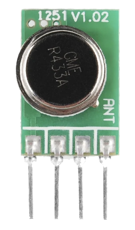
The RF Link Transmitter - 434MHz by WENSHING is a compact and efficient device designed to transmit radio frequency signals at a frequency of 434 MHz. It is widely used in wireless communication systems, including remote controls, sensor networks, and other short-range data transmission applications. This transmitter is ideal for projects requiring low power consumption and reliable communication over moderate distances.
Explore Projects Built with RF Link Transmitter - 434MHz


Explore Projects Built with RF Link Transmitter - 434MHz
Common Applications
- Wireless remote control systems (e.g., garage doors, home automation)
- Sensor data transmission in IoT networks
- Wireless communication between microcontrollers
- Robotics and drone control systems
- Alarm and security systems
Technical Specifications
Below are the key technical details of the RF Link Transmitter - 434MHz:
| Parameter | Value |
|---|---|
| Operating Frequency | 434 MHz |
| Operating Voltage | 3.3V - 12V |
| Operating Current | 9 mA (typical at 5V) |
| Transmission Range | Up to 100 meters (line of sight) |
| Modulation Type | Amplitude Shift Keying (ASK) |
| Data Rate | Up to 10 kbps |
| Dimensions | 19mm x 19mm x 7mm |
Pin Configuration and Descriptions
The RF Link Transmitter has four pins, as described in the table below:
| Pin | Name | Description |
|---|---|---|
| 1 | VCC | Power supply pin. Connect to a voltage source between 3.3V and 12V. |
| 2 | DATA | Data input pin. Connect to the microcontroller or data source. |
| 3 | GND | Ground pin. Connect to the ground of the circuit. |
| 4 | ANT | Antenna pin. Connect to a 17.3 cm wire or a suitable 434 MHz antenna for best performance. |
Usage Instructions
How to Use the RF Link Transmitter in a Circuit
- Power Supply: Connect the VCC pin to a regulated power source (3.3V to 12V). Ensure the power supply is stable to avoid transmission issues.
- Data Input: Connect the DATA pin to the output pin of a microcontroller or other data source. The transmitter will modulate the input signal and transmit it wirelessly.
- Ground Connection: Connect the GND pin to the ground of your circuit.
- Antenna: Attach a 17.3 cm wire or a pre-made 434 MHz antenna to the ANT pin for optimal signal transmission.
Important Considerations and Best Practices
- Antenna Design: Use a properly tuned antenna (17.3 cm for 434 MHz) to maximize range and signal quality.
- Power Supply: Avoid noisy power supplies, as they can interfere with the transmitted signal.
- Data Rate: Ensure the data rate does not exceed 10 kbps for reliable communication.
- Line of Sight: For maximum range, maintain a clear line of sight between the transmitter and receiver.
- Decoupling Capacitor: Add a 0.1 µF capacitor near the VCC pin to filter out power supply noise.
Example: Connecting to an Arduino UNO
Below is an example of how to use the RF Link Transmitter with an Arduino UNO to send data wirelessly:
Circuit Connections
- Connect the VCC pin of the transmitter to the 5V pin on the Arduino.
- Connect the GND pin of the transmitter to the GND pin on the Arduino.
- Connect the DATA pin of the transmitter to digital pin 12 on the Arduino.
- Attach a 17.3 cm wire to the ANT pin for the antenna.
Arduino Code
// Example code to send data using the RF Link Transmitter - 434MHz
// Ensure the receiver is set up to decode the transmitted signal.

#define TRANSMITTER_PIN 12  // Pin connected to the DATA pin of the transmitter

void setup() {
  pinMode(TRANSMITTER_PIN, OUTPUT);  // Set the transmitter pin as an output
}

void loop() {
  // Transmit a HIGH signal for 1 second
  digitalWrite(TRANSMITTER_PIN, HIGH);
  delay(1000);  // Wait for 1 second

  // Transmit a LOW signal for 1 second
  digitalWrite(TRANSMITTER_PIN, LOW);
  delay(1000);  // Wait for 1 second
}
Troubleshooting and FAQs
Common Issues and Solutions
No Signal Transmission
- Cause: Incorrect wiring or loose connections.
- Solution: Double-check all connections, especially the VCC, GND, and DATA pins.
Short Transmission Range
- Cause: Poor antenna design or obstructions in the signal path.
- Solution: Use a properly tuned 17.3 cm antenna and ensure a clear line of sight.
Interference with Other Devices
- Cause: Overlapping frequencies with nearby devices.
- Solution: Ensure no other devices are operating at 434 MHz in the vicinity.
Unstable Signal
- Cause: Noisy power supply or exceeding the data rate limit.
- Solution: Use a decoupling capacitor near the VCC pin and keep the data rate below 10 kbps.
FAQs
Q1: Can I use this transmitter with a 3.3V microcontroller?
A1: Yes, the transmitter operates at voltages as low as 3.3V. Ensure the data signal is also 3.3V compatible.
Q2: What is the maximum range of this transmitter?
A2: The maximum range is approximately 100 meters in an open area with a clear line of sight.
Q3: Do I need a specific receiver for this transmitter?
A3: Yes, you need a compatible 434 MHz RF receiver to decode the transmitted signals.
Q4: Can I transmit audio or video signals with this transmitter?
A4: No, this transmitter is designed for low-speed digital data transmission (up to 10 kbps).
By following this documentation, you can effectively integrate the RF Link Transmitter - 434MHz into your wireless communication projects.