
How to Use Tactile Switch Buttons - 6mm Square: Examples, Pinouts, and Specs
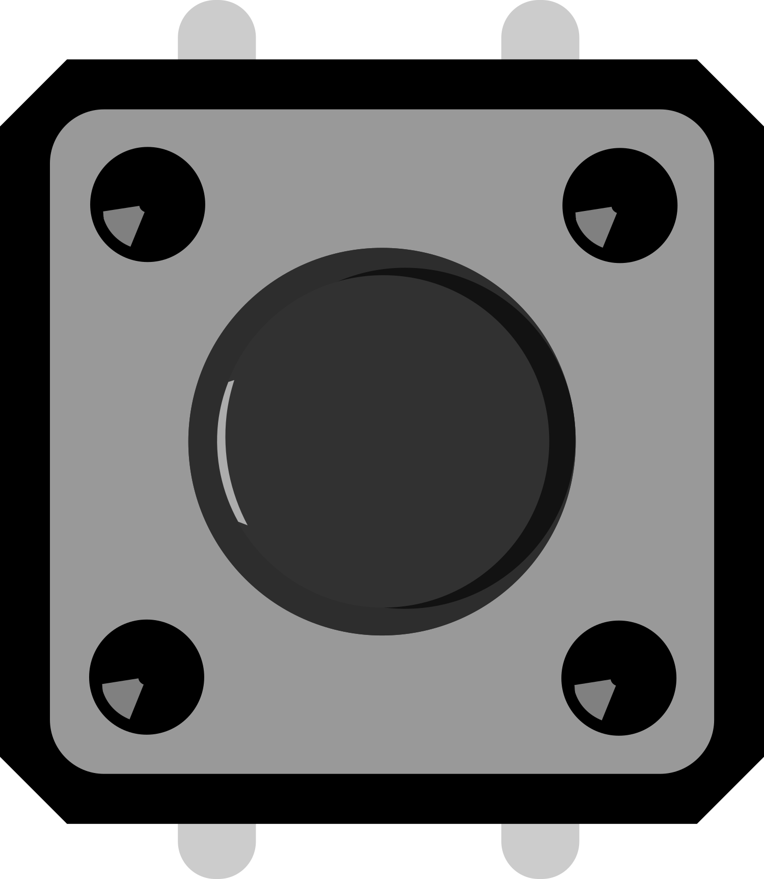
 Design with Tactile Switch Buttons - 6mm Square in Cirkit Designer
Introduction
Tactile Switch Buttons, also known as push-button switches, are compact, momentary switches that provide tactile feedback when pressed. These 6mm square switches are widely used in electronic devices for user interfaces, such as control panels, remote controls, and DIY electronics projects. Their small size, reliability, and ease of use make them a popular choice for hobbyists and professionals alike.
Explore Projects Built with Tactile Switch Buttons - 6mm Square
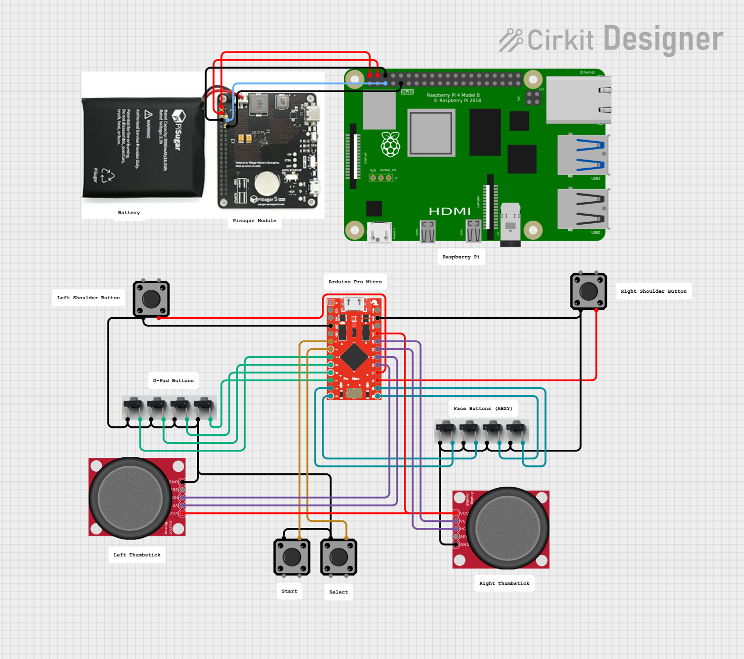 Open Project in Cirkit Designer
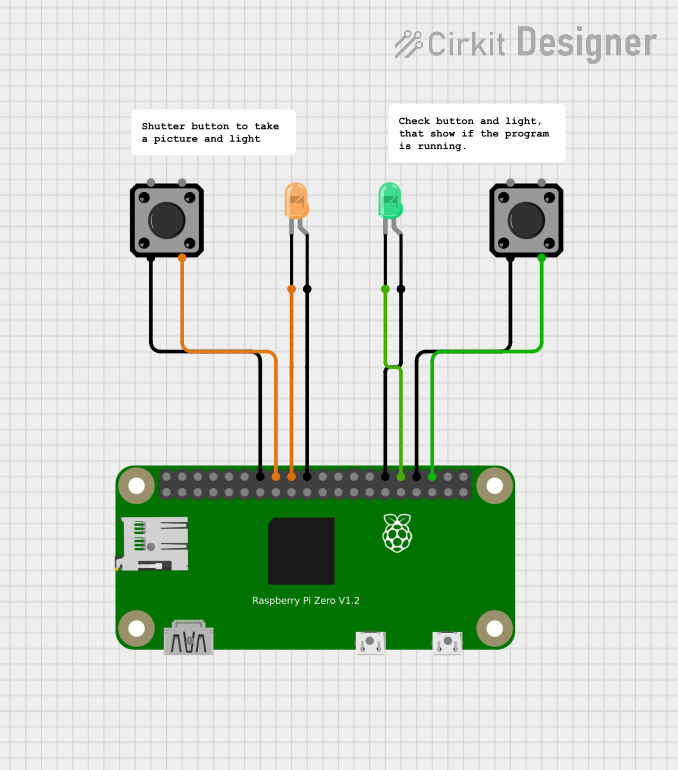 Open Project in Cirkit Designer
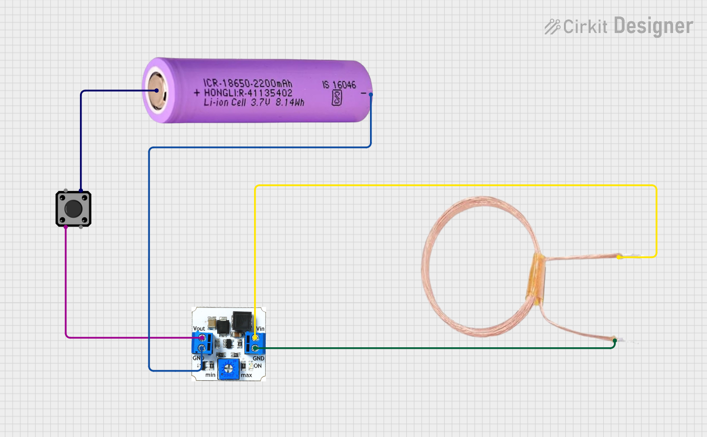 Open Project in Cirkit Designer
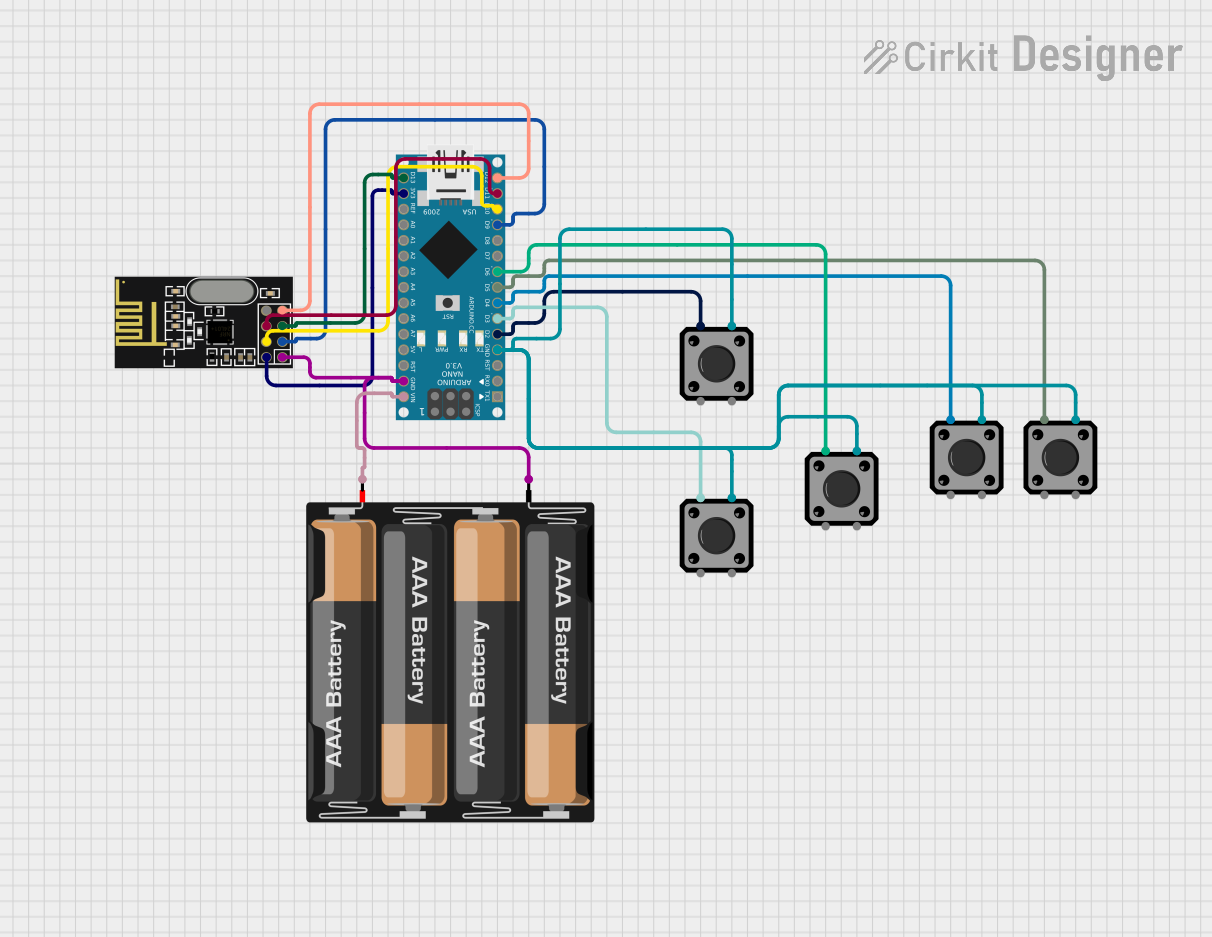 Open Project in Cirkit Designer
Explore Projects Built with Tactile Switch Buttons - 6mm Square
Open Project in Cirkit DesignerOpen Project in Cirkit DesignerOpen Project in Cirkit DesignerOpen Project in Cirkit DesignerCommon Applications:
- User input for microcontroller-based projects (e.g., Arduino, Raspberry Pi)
- Control panels for consumer electronics
- Reset or power buttons in circuits
- Prototyping and breadboard projects
Technical Specifications
Below are the key technical details for the 6mm square tactile switch buttons:
| Parameter | Value |
|---|---|
| Switch Type | Momentary (Normally Open) |
| Dimensions | 6mm x 6mm x 5mm (L x W x H) |
| Operating Voltage | 12V DC (maximum) |
| Operating Current | 50mA (maximum) |
| Contact Resistance | ≤ 100mΩ |
| Insulation Resistance | ≥ 100MΩ |
| Operating Force | 160gf ± 50gf |
| Lifespan | 100,000 cycles (typical) |
| Operating Temperature | -25°C to +70°C |
Pin Configuration and Description
The tactile switch has four pins, arranged in a square configuration. However, only two pins are electrically connected at any given time. The other two pins are redundant and provide mechanical stability.
| Pin Number | Description |
|---|---|
| 1 | Connected to one side of the switch |
| 2 | Connected to the other side of the switch |
| 3 | Redundant (internally connected to Pin 1) |
| 4 | Redundant (internally connected to Pin 2) |
Note: Pins 1 and 3 are internally connected, as are Pins 2 and 4. When the button is pressed, the circuit between Pins 1/3 and Pins 2/4 is completed.
Usage Instructions
How to Use the Tactile Switch in a Circuit
- Identify the Pins: Use a multimeter in continuity mode to identify the connected pairs of pins (Pins 1/3 and Pins 2/4).
- Connect to Circuit:
- Connect one pair of pins (e.g., Pins 1/3) to the input signal or microcontroller pin.
- Connect the other pair (Pins 2/4) to ground or the desired circuit path.
- Debounce the Switch: Tactile switches may produce noise or "bouncing" when pressed. Use a capacitor (e.g., 0.1µF) or software debounce techniques to ensure stable operation.
- Test the Circuit: Verify the switch operation by pressing it and observing the circuit behavior.
Best Practices:
- Pull-Up or Pull-Down Resistors: Use a pull-up or pull-down resistor (typically 10kΩ) to ensure a defined logic level when the switch is not pressed.
- Avoid Overloading: Do not exceed the maximum voltage (12V) or current (50mA) ratings to prevent damage.
- Mounting: Ensure the switch is securely mounted on a PCB or breadboard to avoid mechanical stress.
Example: Connecting to an Arduino UNO
Below is an example of how to connect a tactile switch to an Arduino UNO and read its state:
Circuit Diagram:
- Connect one side of the switch (Pins 1/3) to digital pin 2 on the Arduino.
- Connect the other side (Pins 2/4) to ground.
- Add a 10kΩ pull-up resistor between digital pin 2 and 5V.
Arduino Code:
// Define the pin connected to the tactile switch
const int buttonPin = 2;

// Variable to store the button state
int buttonState = 0;

void setup() {
  // Set the button pin as input with an internal pull-up resistor
  pinMode(buttonPin, INPUT_PULLUP);

  // Initialize serial communication for debugging
  Serial.begin(9600);
}

void loop() {
  // Read the state of the button (LOW when pressed, HIGH when released)
  buttonState = digitalRead(buttonPin);

  // Print the button state to the Serial Monitor
  if (buttonState == LOW) {
    Serial.println("Button Pressed");
  } else {
    Serial.println("Button Released");
  }

  // Add a small delay to avoid spamming the Serial Monitor
  delay(100);
}
Note: The internal pull-up resistor in the Arduino is used to simplify the circuit.
Troubleshooting and FAQs
Common Issues:
Button Not Responding:
- Cause: Incorrect wiring or loose connections.
- Solution: Double-check the pin connections and ensure the switch is securely mounted.
Button Bouncing:
- Cause: Mechanical bouncing of the switch contacts.
- Solution: Use a capacitor for hardware debouncing or implement software debounce logic.
Switch Feels Stiff or Unresponsive:
- Cause: Physical damage or dirt inside the switch.
- Solution: Replace the switch if damaged. Avoid exposing it to dust or moisture.
Arduino Not Detecting Button Press:
- Cause: Missing pull-up or pull-down resistor.
- Solution: Add a pull-up or pull-down resistor to ensure a stable logic level.
FAQs:
Q1: Can I use the tactile switch with higher voltages or currents?
A1: No, the switch is rated for a maximum of 12V and 50mA. Exceeding these limits may damage the switch or cause it to fail.
Q2: How do I debounce the switch in software?
A2: You can use a simple delay after detecting a button press or implement a debounce algorithm that checks for consistent readings over a short period.
Q3: Can I use the tactile switch in an outdoor environment?
A3: These switches are not weatherproof. For outdoor use, consider using a sealed or waterproof switch.
Q4: Are the redundant pins necessary for operation?
A4: No, the redundant pins (Pins 3 and 4) are only for mechanical stability. You can use just Pins 1 and 2 if desired.
By following this documentation, you can effectively integrate and troubleshoot 6mm square tactile switch buttons in your electronic projects.