
How to Use Pre-Assembled Female BNC: Examples, Pinouts, and Specs
 Design with Pre-Assembled Female BNC in Cirkit Designer
Introduction
The Pre-Assembled Female BNC Connector (COM-101), manufactured by Atlas Scientific, is a high-quality coaxial connector designed for reliable and secure cable connections in RF (Radio Frequency) applications. It features a bayonet-style locking mechanism, ensuring a stable and durable connection. This connector is widely used in video transmission, data communication, and laboratory equipment setups.
Explore Projects Built with Pre-Assembled Female BNC
 Open Project in Cirkit Designer
 Open Project in Cirkit Designer
 Open Project in Cirkit Designer
 Open Project in Cirkit Designer
Explore Projects Built with Pre-Assembled Female BNC
Open Project in Cirkit DesignerOpen Project in Cirkit DesignerOpen Project in Cirkit DesignerOpen Project in Cirkit DesignerCommon Applications and Use Cases
- Video Transmission: Used in CCTV systems, broadcast equipment, and video monitors.
- Data Communication: Ideal for connecting oscilloscopes, signal generators, and other test equipment.
- Laboratory and Industrial Applications: Commonly used in pH probes, conductivity sensors, and other scientific instruments.
- RF Applications: Suitable for low-frequency RF signal transmission.
Technical Specifications
Key Technical Details
| Parameter | Specification |
|---|---|
| Manufacturer | Atlas Scientific |
| Part ID | COM-101 |
| Connector Type | Female BNC |
| Locking Mechanism | Bayonet-style |
| Impedance | 50 Ω |
| Frequency Range | DC to 4 GHz |
| Voltage Rating | 500 V peak |
| Material | Nickel-plated brass (body), gold-plated contacts |
| Cable Compatibility | Coaxial cables (RG-58, RG-59, etc.) |
| Operating Temperature | -55°C to +85°C |
Pin Configuration and Descriptions
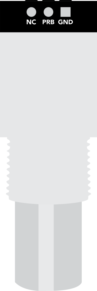
The Pre-Assembled Female BNC connector does not have traditional "pins" like ICs or microcontrollers. Instead, it has two primary connection points:
| Connection Point | Description |
|---|---|
| Center Pin | Carries the signal (positive or data line). |
| Outer Shield | Acts as the ground and provides shielding. |
Usage Instructions
How to Use the Component in a Circuit
- Cable Preparation:
- Use a compatible coaxial cable (e.g., RG-58 or RG-59).
- Strip the cable to expose the center conductor and shield.
- Connection:
- Insert the center conductor into the female BNC connector's center pin.
- Ensure the cable's shield makes contact with the connector's outer shield.
- Secure the connection using the bayonet-style locking mechanism by pushing and twisting the connector until it locks.
- Integration:
- Connect the other end of the cable to the desired device (e.g., oscilloscope, sensor, or video equipment).
- Verify the connection is secure and free from signal interference.
Important Considerations and Best Practices
- Cable Selection: Ensure the coaxial cable matches the impedance (50 Ω) of the BNC connector for optimal performance.
- Signal Integrity: Avoid bending the cable excessively, as this can degrade signal quality.
- Environmental Conditions: Operate the connector within the specified temperature range (-55°C to +85°C).
- Cleaning: Periodically clean the connector contacts with a soft, lint-free cloth to maintain good electrical conductivity.
Example: Connecting to an Arduino UNO
The Pre-Assembled Female BNC connector can be used to interface sensors (e.g., pH probes) with an Arduino UNO. Below is an example of how to read data from a pH sensor connected via the BNC connector.
Arduino Code Example
// Example: Reading pH sensor data via BNC connector
// Ensure the pH sensor is connected to the BNC connector, and the signal pin
// is wired to Arduino analog pin A0.

const int pH_Pin = A0;  // Analog pin connected to the pH sensor
float voltage;          // Variable to store the sensor voltage
float pH_Value;         // Variable to store the calculated pH value

void setup() {
  Serial.begin(9600);  // Initialize serial communication
  Serial.println("pH Sensor Reading via BNC Connector");
}

void loop() {
  // Read the analog voltage from the pH sensor
  int sensorValue = analogRead(pH_Pin);

  // Convert the analog value to voltage (assuming 5V reference)
  voltage = sensorValue * (5.0 / 1023.0);

  // Convert voltage to pH value (example calibration: 0V = pH 0, 5V = pH 14)
  pH_Value = voltage * 14.0 / 5.0;

  // Print the pH value to the Serial Monitor
  Serial.print("Voltage: ");
  Serial.print(voltage, 2);  // Print voltage with 2 decimal places
  Serial.print(" V, pH: ");
  Serial.println(pH_Value, 2);  // Print pH value with 2 decimal places

  delay(1000);  // Wait 1 second before the next reading
}
Troubleshooting and FAQs
Common Issues and Solutions
| Issue | Possible Cause | Solution |
|---|---|---|
| No signal or data transmission | Loose or improper connection | Ensure the BNC connector is securely locked. |
| Signal interference or noise | Poor shielding or damaged cable | Use high-quality coaxial cables and check for damage. |
| Incorrect readings from sensors | Calibration issue or incorrect wiring | Verify sensor calibration and wiring connections. |
| Connector overheating | Exceeding voltage or current ratings | Ensure the voltage and current are within specified limits. |
FAQs
Can this connector be used with 75 Ω cables?
- While the connector is designed for 50 Ω impedance, it can physically connect to 75 Ω cables. However, this may result in signal reflections and reduced performance.
How do I clean the connector?
- Use a soft, lint-free cloth and isopropyl alcohol to clean the contacts. Avoid abrasive materials.
Is this connector waterproof?
- No, the COM-101 is not waterproof. Use it in dry environments or protect it with appropriate enclosures.
What is the maximum frequency this connector supports?
- The COM-101 supports frequencies up to 4 GHz, making it suitable for most RF applications.
By following this documentation, users can effectively integrate the Pre-Assembled Female BNC Connector (COM-101) into their projects and ensure reliable performance.