Cirkit Designer Logo
Cirkit Designer
Your all-in-one circuit design IDE
Home / 
Component Documentation

How to Use S7-PM1207: Examples, Pinouts, and Specs

Image of S7-PM1207
Cirkit Designer LogoDesign with S7-PM1207 in Cirkit Designer

Introduction

The S7-PM1207 is a power supply module manufactured by Siemens, specifically designed for use with the Siemens S7-1200 Programmable Logic Controller (PLC) systems. This module provides a stable and reliable DC output voltage, ensuring the proper operation of connected devices and components in industrial automation applications. Its compact design and robust performance make it an essential component for powering automation systems in various industries.

Explore Projects Built with S7-PM1207

Use Cirkit Designer to design, explore, and prototype these projects online. Some projects support real-time simulation. Click "Open Project" to start designing instantly!
Battery-Powered Emergency Alert System with NUCLEO-F072RB, SIM800L, and GPS NEO 6M
Image of women safety: A project utilizing S7-PM1207 in a practical application
This circuit is an emergency alert system that uses a NUCLEO-F072RB microcontroller to send SMS alerts and make calls via a SIM800L GSM module, while obtaining location data from a GPS NEO 6M module. The system is powered by a Li-ion battery and includes a TP4056 module for battery charging and protection, with a rocker switch to control power to the microcontroller.
Cirkit Designer LogoOpen Project in Cirkit Designer
Battery-Powered 18650 Li-ion Charger with USB Output and Adjustable Voltage Regulator
Image of Breadboard: A project utilizing S7-PM1207 in a practical application
This circuit is a battery management and power supply system that uses three 3.7V batteries connected to a 3S 10A Li-ion 18650 Charger Protection Board Module for balanced charging and protection. The system includes a TP4056 Battery Charging Protection Module for additional charging safety, a Step Up Boost Power Converter to regulate and boost the voltage, and a USB regulator to provide a stable 5V output, controlled by a push switch.
Cirkit Designer LogoOpen Project in Cirkit Designer
Cellular-Enabled IoT Device with Real-Time Clock and Power Management
Image of LRCM PHASE 2 BASIC: A project utilizing S7-PM1207 in a practical application
This circuit features a LilyGo-SIM7000G module for cellular communication and GPS functionality, interfaced with an RTC DS3231 for real-time clock capabilities. It includes voltage sensing through two voltage sensor modules, and uses an 8-channel opto-coupler for isolating different parts of the circuit. Power management is handled by a buck converter connected to a DC power source and batteries, with a fuse for protection and a rocker switch for on/off control. Additionally, there's an LED for indication purposes.
Cirkit Designer LogoOpen Project in Cirkit Designer
Solar-Powered Li-ion Battery Charger with TP4056
Image of pdb solar power bank: A project utilizing S7-PM1207 in a practical application
This circuit consists of a solar panel, a Li-ion battery, and a TP4056 charging module. The solar panel charges the Li-ion battery through the TP4056 module, which manages the charging process to ensure safe and efficient charging of the battery.
Cirkit Designer LogoOpen Project in Cirkit Designer

Explore Projects Built with S7-PM1207

Use Cirkit Designer to design, explore, and prototype these projects online. Some projects support real-time simulation. Click "Open Project" to start designing instantly!
Image of women safety: A project utilizing S7-PM1207 in a practical application
Battery-Powered Emergency Alert System with NUCLEO-F072RB, SIM800L, and GPS NEO 6M
This circuit is an emergency alert system that uses a NUCLEO-F072RB microcontroller to send SMS alerts and make calls via a SIM800L GSM module, while obtaining location data from a GPS NEO 6M module. The system is powered by a Li-ion battery and includes a TP4056 module for battery charging and protection, with a rocker switch to control power to the microcontroller.
Cirkit Designer LogoOpen Project in Cirkit Designer
Image of Breadboard: A project utilizing S7-PM1207 in a practical application
Battery-Powered 18650 Li-ion Charger with USB Output and Adjustable Voltage Regulator
This circuit is a battery management and power supply system that uses three 3.7V batteries connected to a 3S 10A Li-ion 18650 Charger Protection Board Module for balanced charging and protection. The system includes a TP4056 Battery Charging Protection Module for additional charging safety, a Step Up Boost Power Converter to regulate and boost the voltage, and a USB regulator to provide a stable 5V output, controlled by a push switch.
Cirkit Designer LogoOpen Project in Cirkit Designer
Image of LRCM PHASE 2 BASIC: A project utilizing S7-PM1207 in a practical application
Cellular-Enabled IoT Device with Real-Time Clock and Power Management
This circuit features a LilyGo-SIM7000G module for cellular communication and GPS functionality, interfaced with an RTC DS3231 for real-time clock capabilities. It includes voltage sensing through two voltage sensor modules, and uses an 8-channel opto-coupler for isolating different parts of the circuit. Power management is handled by a buck converter connected to a DC power source and batteries, with a fuse for protection and a rocker switch for on/off control. Additionally, there's an LED for indication purposes.
Cirkit Designer LogoOpen Project in Cirkit Designer
Image of pdb solar power bank: A project utilizing S7-PM1207 in a practical application
Solar-Powered Li-ion Battery Charger with TP4056
This circuit consists of a solar panel, a Li-ion battery, and a TP4056 charging module. The solar panel charges the Li-ion battery through the TP4056 module, which manages the charging process to ensure safe and efficient charging of the battery.
Cirkit Designer LogoOpen Project in Cirkit Designer

Common Applications and Use Cases

  • Powering Siemens S7-1200 PLC systems in industrial automation setups.
  • Providing stable DC power for sensors, actuators, and other peripheral devices.
  • Ensuring reliable operation in manufacturing, process control, and building automation systems.
  • Suitable for environments requiring high reliability and minimal downtime.

Technical Specifications

Key Technical Details

Parameter Value
Input Voltage Range 85–264 VAC (47–63 Hz)
Output Voltage 24 VDC
Output Current 2.5 A
Power Output 60 W
Efficiency > 90%
Operating Temperature -20°C to +70°C
Storage Temperature -40°C to +85°C
Dimensions (W x H x D) 70 mm x 100 mm x 75 mm
Weight Approximately 0.4 kg
Certifications CE, UL, cULus, and RoHS

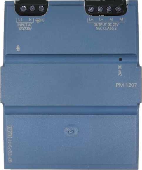
Pin Configuration and Descriptions

The S7-PM1207 module features screw terminals for input and output connections. Below is the pin configuration:

Input Terminals

Terminal Label Description
L Live AC input (85–264 VAC)
N Neutral AC input
PE Protective Earth (Ground)

Output Terminals

Terminal Label Description
+24V Positive DC output (24 VDC)
0V Negative DC output (Ground)

Usage Instructions

How to Use the S7-PM1207 in a Circuit

  1. Mounting the Module: Secure the S7-PM1207 module onto a DIN rail or a flat surface using the provided mounting brackets. Ensure proper ventilation around the module to prevent overheating.
  2. Connecting the Input:
    • Connect the AC power source to the input terminals (L, N, and PE).
    • Ensure the input voltage is within the specified range (85–264 VAC).
  3. Connecting the Output:
    • Connect the +24V terminal to the positive input of the load (e.g., PLC, sensors).
    • Connect the 0V terminal to the ground of the load.
  4. Powering On:
    • After verifying all connections, switch on the AC power supply.
    • The module will provide a stable 24 VDC output to the connected devices.

Important Considerations and Best Practices

  • Overload Protection: The S7-PM1207 includes built-in overload and short-circuit protection. Ensure the total load does not exceed the maximum output current of 2.5 A.
  • Ventilation: Maintain adequate airflow around the module to prevent overheating. Avoid installing the module in enclosed spaces without proper ventilation.
  • Grounding: Properly connect the PE terminal to the protective earth to ensure safety and reduce electrical noise.
  • Wiring: Use appropriately rated wires for both input and output connections to handle the current and voltage safely.

Example: Connecting to an S7-1200 PLC

The S7-PM1207 is commonly used to power Siemens S7-1200 PLC systems. Below is an example of how to connect the power supply to the PLC:

  1. Connect the +24V terminal of the S7-PM1207 to the L+ terminal of the S7-1200 PLC.
  2. Connect the 0V terminal of the S7-PM1207 to the M terminal of the S7-1200 PLC.
  3. Ensure the AC input is properly connected to the S7-PM1207 as described earlier.

Troubleshooting and FAQs

Common Issues and Solutions

Issue Possible Cause Solution
No output voltage Input power not connected or faulty Verify AC input connections and voltage.
Output voltage is unstable Overload or short circuit on the output Reduce the load or check for short circuits.
Module overheating Insufficient ventilation or high ambient temperature Improve airflow or reduce ambient temperature.
PLC not powering on Incorrect wiring or insufficient output current Verify connections and ensure load is within limits.

FAQs

Q1: Can the S7-PM1207 power multiple devices simultaneously?
A1: Yes, as long as the total current draw does not exceed 2.5 A. Use proper wiring to distribute the power.

Q2: Is the S7-PM1207 suitable for outdoor use?
A2: The module is not designed for direct outdoor use. If outdoor installation is required, ensure it is housed in a weatherproof enclosure.

Q3: What happens if the input voltage exceeds 264 VAC?
A3: The module may shut down or get damaged. Always ensure the input voltage is within the specified range.

Q4: How do I reset the module after a short circuit?
A4: Disconnect the load, resolve the short circuit, and then reconnect the load. The module will automatically recover.

Q5: Can I use the S7-PM1207 with non-Siemens devices?
A5: Yes, the S7-PM1207 can power any device requiring 24 VDC, provided the current draw is within the 2.5 A limit.