Cirkit Designer Logo
Cirkit Designer
Your all-in-one circuit design IDE
Home / 
Component Documentation

How to Use XL6009 Voltage Regulator: Examples, Pinouts, and Specs

Image of XL6009 Voltage Regulator
Cirkit Designer LogoDesign with XL6009 Voltage Regulator in Cirkit Designer

Introduction

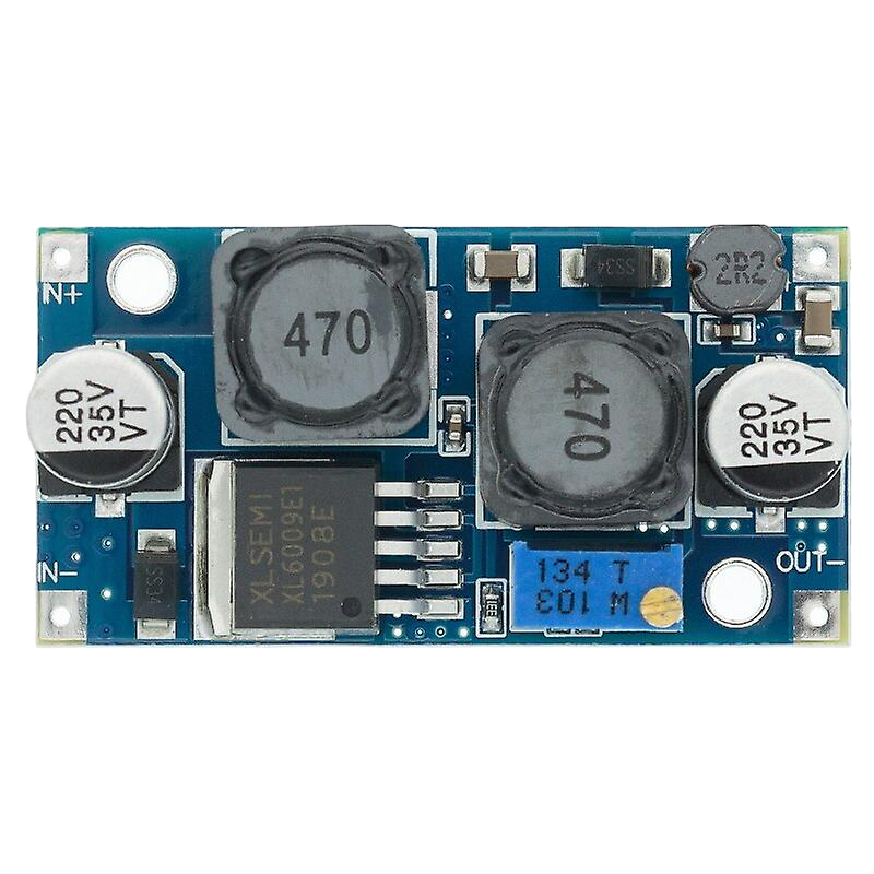
The XL6009 Voltage Regulator is a high-efficiency, adjustable step-up DC-DC converter module. It is designed to provide a higher output voltage than the input voltage it receives. This component is commonly used in battery-powered devices, solar power systems, and applications requiring voltage step-up conversion for driving electronics that operate at a higher voltage than the power source.

Explore Projects Built with XL6009 Voltage Regulator

Use Cirkit Designer to design, explore, and prototype these projects online. Some projects support real-time simulation. Click "Open Project" to start designing instantly!
Solar-Powered Battery Charging System with XL6009 Voltage Regulator
Image of SISTEMA DE ALIMENTACION Y CARGA SENSORES DS18B20 Y SENSOR DE TURBIDEZ: A project utilizing XL6009 Voltage Regulator in a practical application
This circuit features a solar panel ('Do solara') connected to a voltage regulator ('XL6009 Voltage Regulator') to stabilize the output voltage. The regulated voltage is available at a terminal block ('Terminal PCB 2 Pin') for further use. Additionally, a Li-ion battery ('18650 Li-ion Battery') is connected to the solar panel for charging, with the solar panel's output also routed through the voltage regulator.
Cirkit Designer LogoOpen Project in Cirkit Designer
Dual ESP32-CAM Module with 12V Battery and Voltage Regulation
Image of capstone esp32: A project utilizing XL6009 Voltage Regulator in a practical application
This circuit consists of a 12V 200Ah battery connected to an XL6009 voltage regulator, which steps up or down the voltage to a regulated output. The regulated output from the XL6009 is then used to power two ESP32 CAM modules. The circuit is designed to provide a stable 5V power supply to the ESP32 CAM modules from the 12V battery source.
Cirkit Designer LogoOpen Project in Cirkit Designer
12V UPS System with Dual 18650 Li-ion Battery Backup and Voltage Regulation
Image of Power supply: A project utilizing XL6009 Voltage Regulator in a practical application
This circuit is designed to provide an uninterruptible power supply (UPS) system with a 12V DC output. It includes a 12V 5A power supply connected to an AC source through a toggle switch, which charges a pair of 18650 Li-ion batteries via a voltage regulator (XL4016). The UPS module ensures a continuous power supply to the load by switching between the power supply and the battery bank.
Cirkit Designer LogoOpen Project in Cirkit Designer
LM317 Voltage Regulator Circuit for Adjustable Power Supply with Transformer and Diodes
Image of 12V BULB LIGHT DIMMER CIRCUIT: A project utilizing XL6009 Voltage Regulator in a practical application
This circuit is a regulated power supply that converts AC voltage to a stable DC voltage. It uses a transformer to step down the AC voltage, diodes for rectification, an electrolytic capacitor for smoothing, and an LM317 voltage regulator to provide a stable output voltage, which is adjustable via a potentiometer. The output powers a bulb.
Cirkit Designer LogoOpen Project in Cirkit Designer

Explore Projects Built with XL6009 Voltage Regulator

Use Cirkit Designer to design, explore, and prototype these projects online. Some projects support real-time simulation. Click "Open Project" to start designing instantly!
Image of SISTEMA DE ALIMENTACION Y CARGA SENSORES DS18B20 Y SENSOR DE TURBIDEZ: A project utilizing XL6009 Voltage Regulator in a practical application
Solar-Powered Battery Charging System with XL6009 Voltage Regulator
This circuit features a solar panel ('Do solara') connected to a voltage regulator ('XL6009 Voltage Regulator') to stabilize the output voltage. The regulated voltage is available at a terminal block ('Terminal PCB 2 Pin') for further use. Additionally, a Li-ion battery ('18650 Li-ion Battery') is connected to the solar panel for charging, with the solar panel's output also routed through the voltage regulator.
Cirkit Designer LogoOpen Project in Cirkit Designer
Image of capstone esp32: A project utilizing XL6009 Voltage Regulator in a practical application
Dual ESP32-CAM Module with 12V Battery and Voltage Regulation
This circuit consists of a 12V 200Ah battery connected to an XL6009 voltage regulator, which steps up or down the voltage to a regulated output. The regulated output from the XL6009 is then used to power two ESP32 CAM modules. The circuit is designed to provide a stable 5V power supply to the ESP32 CAM modules from the 12V battery source.
Cirkit Designer LogoOpen Project in Cirkit Designer
Image of Power supply: A project utilizing XL6009 Voltage Regulator in a practical application
12V UPS System with Dual 18650 Li-ion Battery Backup and Voltage Regulation
This circuit is designed to provide an uninterruptible power supply (UPS) system with a 12V DC output. It includes a 12V 5A power supply connected to an AC source through a toggle switch, which charges a pair of 18650 Li-ion batteries via a voltage regulator (XL4016). The UPS module ensures a continuous power supply to the load by switching between the power supply and the battery bank.
Cirkit Designer LogoOpen Project in Cirkit Designer
Image of 12V BULB LIGHT DIMMER CIRCUIT: A project utilizing XL6009 Voltage Regulator in a practical application
LM317 Voltage Regulator Circuit for Adjustable Power Supply with Transformer and Diodes
This circuit is a regulated power supply that converts AC voltage to a stable DC voltage. It uses a transformer to step down the AC voltage, diodes for rectification, an electrolytic capacitor for smoothing, and an LM317 voltage regulator to provide a stable output voltage, which is adjustable via a potentiometer. The output powers a bulb.
Cirkit Designer LogoOpen Project in Cirkit Designer

Common Applications and Use Cases

  • Battery-powered devices requiring a higher operating voltage
  • Solar power systems for voltage step-up
  • Powering devices from a lower voltage source
  • Portable electronics
  • DIY electronics projects

Technical Specifications

The XL6009 Voltage Regulator has several key technical specifications that are crucial for its operation. Below are the specifications and a pin configuration table.

Key Technical Details

  • Input Voltage Range: 3V to 32V
  • Output Voltage Range: 5V to 35V (adjustable via onboard potentiometer)
  • Maximum Output Current: Up to 4A (dependent on input/output voltage differential and heat dissipation)
  • Switching Frequency: 400kHz
  • Efficiency: Up to 94% (varies based on load and voltage settings)
  • Operating Temperature: -40°C to +85°C

Pin Configuration and Descriptions

Pin Number Name Description
1 GND Ground connection for the module.
2 VIN Input voltage to the module (3V to 32V).
3 VOUT Output voltage from the module (5V to 35V).
4 EN Enable pin for turning the module on/off. Pulling this pin low disables the module.

Usage Instructions

How to Use the Component in a Circuit

  1. Connect the input voltage source to the VIN and GND pins, ensuring that the voltage is within the specified range.
  2. Connect the load to the VOUT and GND pins.
  3. Adjust the onboard potentiometer to set the desired output voltage. Use a multimeter to monitor the output voltage while adjusting.
  4. Optionally, connect a switch or microcontroller output to the EN pin for enabling or disabling the module.

Important Considerations and Best Practices

  • Always verify input and output voltages with a multimeter before connecting sensitive electronics.
  • Ensure adequate heat dissipation if the module is expected to deliver high current or if there is a significant voltage difference between input and output.
  • Avoid adjusting the potentiometer while the module is under load to prevent voltage spikes.
  • Keep the input voltage below the maximum rating to prevent damage to the module.

Troubleshooting and FAQs

Common Issues

  • Output voltage is not stable or does not match the setting: Ensure that the potentiometer is properly adjusted and that the input voltage is stable and within the specified range.
  • Module is overheating: Check if the current draw is within the module's limits and improve heat dissipation with a heatsink or by reducing the load.

Solutions and Tips for Troubleshooting

  • If the output voltage is too low, check the input voltage and adjust the potentiometer carefully.
  • If the module does not power on, verify connections to the EN pin and ensure it is pulled high.
  • For thermal issues, consider adding a heatsink or reducing the load to lower the temperature.

FAQs

Q: Can I use the XL6009 to step down voltage? A: No, the XL6009 is a step-up (boost) converter and cannot be used to lower voltage.

Q: How do I enable or disable the module using a microcontroller? A: Connect the EN pin to a digital output pin on the microcontroller. Set the pin high to enable and low to disable the module.

Q: What is the maximum output current of the XL6009? A: The XL6009 can deliver up to 4A, but this is dependent on input/output voltage differential and adequate heat dissipation.

Q: How can I improve the efficiency of the XL6009? A: Efficiency can be improved by ensuring the input voltage is as close as possible to the desired output voltage, reducing the load, and optimizing the layout for minimal resistance and inductance paths.

Example Arduino Connection (Optional)

If you're using the XL6009 with an Arduino UNO, you can control the EN pin to turn the voltage regulator on and off programmatically. Here's a simple example code snippet:

const int enablePin = 7; // Connect the EN pin of XL6009 to digital pin 7

void setup() {
  pinMode(enablePin, OUTPUT);
  digitalWrite(enablePin, HIGH); // Enable the XL6009
}

void loop() {
  // Your code here to control the XL6009
  // Use digitalWrite(enablePin, LOW) to disable the XL6009
  // Use digitalWrite(enablePin, HIGH) to enable it again
}

Remember to ensure that the connections are secure and that the input voltage to the Arduino is within its operating range to prevent damage to the board or the XL6009 module.