How to Use Joystick: Examples, Pinouts, and Specs
Introduction
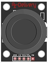
The AZDelivery Joystick (Part ID: Joystick) is an input device designed for precise control in applications such as video games, robotics, and computer graphics. It features a pivoting stick that allows users to report directional input and button presses to the connected system. This versatile component is widely used in projects requiring analog and digital input, making it a popular choice for hobbyists and professionals alike.
Explore Projects Built with Joystick


Explore Projects Built with Joystick
Common Applications and Use Cases
- Game controllers and arcade systems
- Robotics and remote-controlled vehicles
- Computer-aided design (CAD) systems
- DIY electronics projects
- Interactive art installations
Technical Specifications
The AZDelivery Joystick is a dual-axis analog joystick with a built-in push-button. It provides two potentiometers for X and Y axis control and a digital switch for the button press.
Key Technical Details
- Operating Voltage: 3.3V to 5V
- Output Type: Analog (X and Y axes), Digital (button)
- X and Y Axis Range: 0V to Vcc (typically 0V to 5V)
- Button Type: Momentary push-button
- Dimensions: 40mm x 26mm x 32mm (approx.)
- Mounting: PCB with soldered pins
Pin Configuration and Descriptions
The joystick has a total of 5 pins. Below is the pinout and description:
| Pin | Name | Type | Description |
|---|---|---|---|
| 1 | GND | Power | Ground connection for the joystick |
| 2 | +5V | Power | Power supply (3.3V to 5V) |
| 3 | VRx | Analog Output | Voltage output for the X-axis (0V to Vcc) |
| 4 | VRy | Analog Output | Voltage output for the Y-axis (0V to Vcc) |
| 5 | SW | Digital Output | Digital signal for the push-button (LOW when pressed) |
Usage Instructions
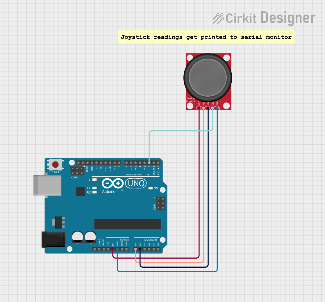
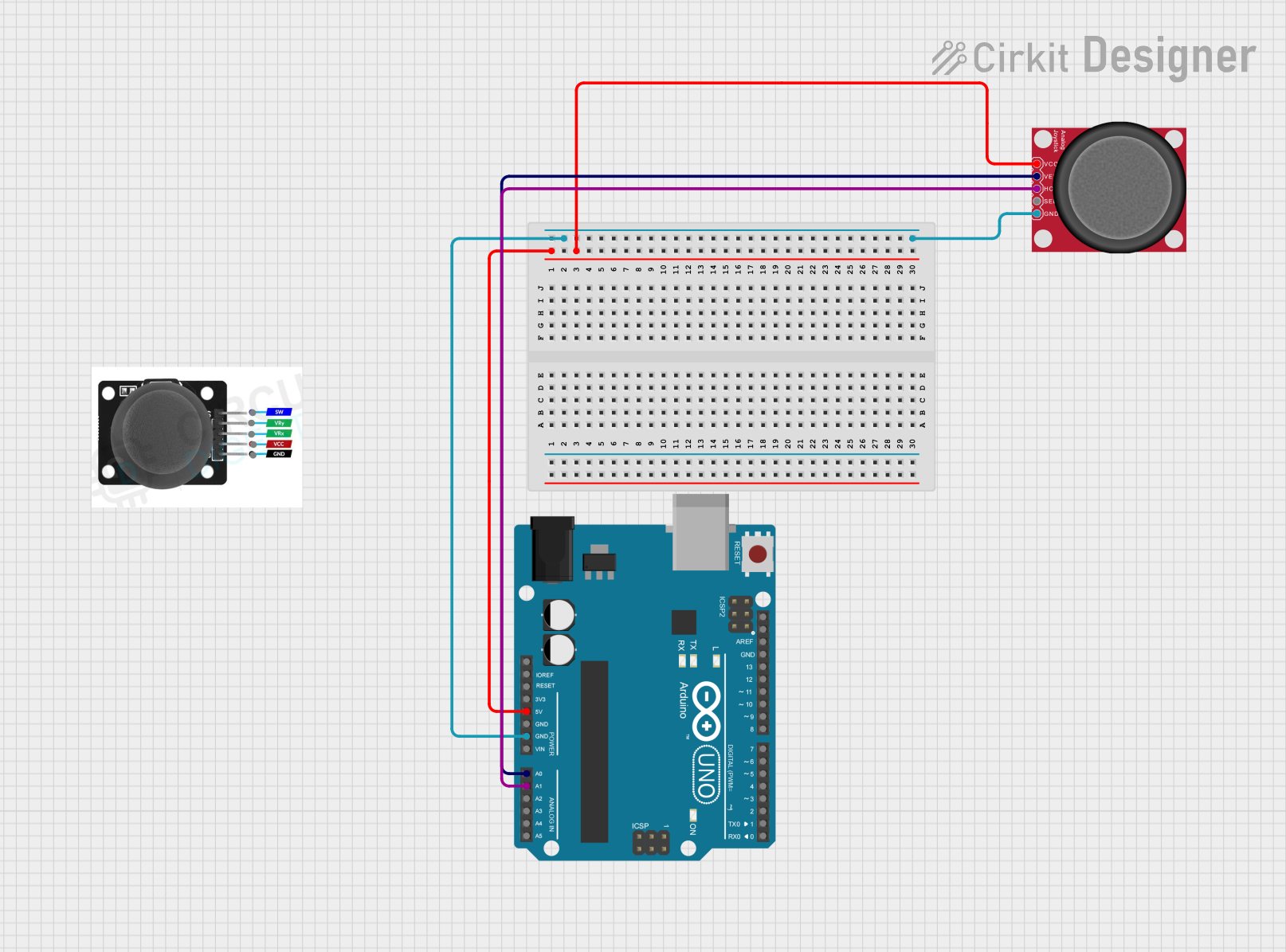
How to Use the Joystick in a Circuit
- Connect Power:
- Connect the
+5Vpin to the 5V output of your microcontroller (e.g., Arduino UNO). - Connect the
GNDpin to the ground of your microcontroller.
- Connect the
- Connect the Axes:
- Connect the
VRxpin to an analog input pin on your microcontroller (e.g., A0 on Arduino UNO). - Connect the
VRypin to another analog input pin (e.g., A1 on Arduino UNO).
- Connect the
- Connect the Button:
- Connect the
SWpin to a digital input pin on your microcontroller (e.g., D2 on Arduino UNO). - Use a pull-up resistor if necessary, as the button outputs LOW when pressed.
- Connect the
Important Considerations and Best Practices
- Ensure the joystick is powered within its operating voltage range (3.3V to 5V).
- Use analog pins on your microcontroller to read the X and Y axis values.
- Debounce the button input in software to avoid false triggers.
- Avoid applying excessive force to the joystick to prevent damage.
Example Code for Arduino UNO
Below is an example Arduino sketch to read the joystick's X and Y axes and detect button presses:
// Define pin connections
const int VRxPin = A0; // X-axis connected to analog pin A0
const int VRyPin = A1; // Y-axis connected to analog pin A1
const int SWPin = 2;   // Button connected to digital pin 2

void setup() {
  // Initialize serial communication for debugging
  Serial.begin(9600);

  // Configure the button pin as input with internal pull-up resistor
  pinMode(SWPin, INPUT_PULLUP);
}

void loop() {
  // Read the X and Y axis values (0 to 1023)
  int xValue = analogRead(VRxPin);
  int yValue = analogRead(VRyPin);

  // Read the button state (LOW when pressed)
  bool buttonPressed = (digitalRead(SWPin) == LOW);

  // Print the joystick values to the Serial Monitor
  Serial.print("X: ");
  Serial.print(xValue);
  Serial.print(" | Y: ");
  Serial.print(yValue);
  Serial.print(" | Button: ");
  Serial.println(buttonPressed ? "Pressed" : "Released");

  // Add a small delay for stability
  delay(100);
}
Troubleshooting and FAQs
Common Issues and Solutions
No Output from the Joystick:
- Ensure the joystick is properly powered (check the
+5VandGNDconnections). - Verify that the pins are securely connected to the microcontroller.
- Ensure the joystick is properly powered (check the
Incorrect or Erratic Axis Readings:
- Check for loose or faulty connections on the
VRxandVRypins. - Ensure the joystick is not damaged or worn out.
- Check for loose or faulty connections on the
Button Not Responding:
- Verify the
SWpin connection and ensure it is configured as an input. - Use a pull-up resistor if the button state is not being detected correctly.
- Verify the
Joystick Values Not Centered:
- The joystick may not return perfectly centered values when released.
- Use software calibration to adjust for any offset.
FAQs
Q: Can I use the joystick with a 3.3V microcontroller?
A: Yes, the joystick operates within a voltage range of 3.3V to 5V, making it compatible with 3.3V systems like ESP32 or Raspberry Pi.
Q: How do I calibrate the joystick?
A: Read the X and Y axis values when the joystick is in its neutral position. Use these values as the center point in your software.
Q: Can I use the joystick for PWM control?
A: Yes, you can map the analog output values from the joystick to control PWM signals for applications like motor speed control.
Q: Is the joystick suitable for outdoor use?
A: The joystick is not weatherproof. For outdoor applications, consider using a protective enclosure.