Cirkit Designer Logo
Cirkit Designer
Your all-in-one circuit design IDE
Home / 
Component Documentation

How to Use ADS7830: Examples, Pinouts, and Specs

Image of ADS7830
Cirkit Designer LogoDesign with ADS7830 in Cirkit Designer

Introduction

The ADS7830, manufactured by Freenove, is a 12-bit analog-to-digital converter (ADC) with a serial interface. It operates on a single supply voltage and is designed for low-power applications. The ADS7830 provides high accuracy and fast conversion rates, making it ideal for use in data acquisition systems, sensor interfacing, and portable devices.

Explore Projects Built with ADS7830

Use Cirkit Designer to design, explore, and prototype these projects online. Some projects support real-time simulation. Click "Open Project" to start designing instantly!
ESP32 and ADXL343-Based Battery-Powered Accelerometer with SPI Communication
Image of vibration module: A project utilizing ADS7830 in a practical application
This circuit features an ESP32 microcontroller interfaced with an ADXL343 accelerometer via SPI communication, powered by a 12V battery regulated down to 5V and 8V using 7805 and 7808 voltage regulators. The ESP32 reads accelerometer data and outputs it via serial communication, with additional components including a pushbutton and a rocker switch for user input.
Cirkit Designer LogoOpen Project in Cirkit Designer
ESP32-Controlled Smart Lighting System with Power Monitoring
Image of Energy Monitoring System: A project utilizing ADS7830 in a practical application
This circuit appears to be a multi-channel current monitoring system using several ACS712 current sensors to measure the current through different loads, likely bulbs connected to a 220V power source. The current readings from the sensors are digitized by an Adafruit ADS1115 16-bit ADC, which interfaces with an ESP32 microcontroller via I2C communication for further processing or telemetry. A buck converter is used to step down the voltage to power the ESP32 and the sensors, and the system is powered through a 2.1mm DC barrel jack, indicating it is designed for external power supply.
Cirkit Designer LogoOpen Project in Cirkit Designer
ESP32-Based Multi-Sensor Monitoring System with Battery Power
Image of Wind turbine 2.0: A project utilizing ADS7830 in a practical application
This circuit is a sensor monitoring system powered by a 7.4V battery, regulated to 5V using a 7805 voltage regulator. It uses an ESP32 microcontroller to interface with an ADXL345 accelerometer, INA219 current sensor, BMP280 pressure sensor, and an IR sensor, all connected via I2C and GPIO for data acquisition and processing.
Cirkit Designer LogoOpen Project in Cirkit Designer
Smart Weighing System with ESP8266 and HX711 - Battery Powered and Wi-Fi Enabled
Image of gggg: A project utilizing ADS7830 in a practical application
This circuit is a multi-sensor data acquisition system powered by a 18650 battery and managed by an ESP8266 microcontroller. It includes a load sensor interfaced with an HX711 module for weight measurement, an IR sensor, an ADXL345 accelerometer, a VL53L0X distance sensor, and a Neo 6M GPS module for location tracking. The system is designed for wireless data transmission and is supported by a TP4056 module for battery charging.
Cirkit Designer LogoOpen Project in Cirkit Designer

Explore Projects Built with ADS7830

Use Cirkit Designer to design, explore, and prototype these projects online. Some projects support real-time simulation. Click "Open Project" to start designing instantly!
Image of vibration module: A project utilizing ADS7830 in a practical application
ESP32 and ADXL343-Based Battery-Powered Accelerometer with SPI Communication
This circuit features an ESP32 microcontroller interfaced with an ADXL343 accelerometer via SPI communication, powered by a 12V battery regulated down to 5V and 8V using 7805 and 7808 voltage regulators. The ESP32 reads accelerometer data and outputs it via serial communication, with additional components including a pushbutton and a rocker switch for user input.
Cirkit Designer LogoOpen Project in Cirkit Designer
Image of Energy Monitoring System: A project utilizing ADS7830 in a practical application
ESP32-Controlled Smart Lighting System with Power Monitoring
This circuit appears to be a multi-channel current monitoring system using several ACS712 current sensors to measure the current through different loads, likely bulbs connected to a 220V power source. The current readings from the sensors are digitized by an Adafruit ADS1115 16-bit ADC, which interfaces with an ESP32 microcontroller via I2C communication for further processing or telemetry. A buck converter is used to step down the voltage to power the ESP32 and the sensors, and the system is powered through a 2.1mm DC barrel jack, indicating it is designed for external power supply.
Cirkit Designer LogoOpen Project in Cirkit Designer
Image of Wind turbine 2.0: A project utilizing ADS7830 in a practical application
ESP32-Based Multi-Sensor Monitoring System with Battery Power
This circuit is a sensor monitoring system powered by a 7.4V battery, regulated to 5V using a 7805 voltage regulator. It uses an ESP32 microcontroller to interface with an ADXL345 accelerometer, INA219 current sensor, BMP280 pressure sensor, and an IR sensor, all connected via I2C and GPIO for data acquisition and processing.
Cirkit Designer LogoOpen Project in Cirkit Designer
Image of gggg: A project utilizing ADS7830 in a practical application
Smart Weighing System with ESP8266 and HX711 - Battery Powered and Wi-Fi Enabled
This circuit is a multi-sensor data acquisition system powered by a 18650 battery and managed by an ESP8266 microcontroller. It includes a load sensor interfaced with an HX711 module for weight measurement, an IR sensor, an ADXL345 accelerometer, a VL53L0X distance sensor, and a Neo 6M GPS module for location tracking. The system is designed for wireless data transmission and is supported by a TP4056 module for battery charging.
Cirkit Designer LogoOpen Project in Cirkit Designer

Common Applications

  • Sensor data acquisition (e.g., temperature, pressure, light sensors)
  • Portable and battery-powered devices
  • Industrial process control
  • Medical instrumentation
  • IoT devices requiring analog signal conversion

Technical Specifications

The ADS7830 is a versatile ADC with the following key specifications:

Parameter Value
Resolution 12-bit
Number of Channels 8 (multiplexed)
Supply Voltage Range 2.7V to 5.5V
Input Voltage Range 0V to VDD
Conversion Time 25 µs (typical)
Communication Interface I²C
Power Consumption 0.3 mW (typical at 3V)
Operating Temperature Range -40°C to +85°C
Package Type SOP-16

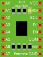
Pin Configuration and Descriptions

The ADS7830 comes in a 16-pin SOP package. Below is the pin configuration:

Pin Number Pin Name Description
1 A0 I²C Address Selection Pin (LSB of address)
2 A1 I²C Address Selection Pin (MSB of address)
3 SDA Serial Data Line for I²C Communication
4 SCL Serial Clock Line for I²C Communication
5-12 CH0-CH7 Analog Input Channels (CH0 to CH7)
13 VDD Positive Supply Voltage
14 GND Ground
15 REF Reference Voltage Input
16 NC No Connection

Usage Instructions

How to Use the ADS7830 in a Circuit

  1. Power Supply: Connect the VDD pin to a stable power source (2.7V to 5.5V) and the GND pin to ground.
  2. Reference Voltage: Provide a reference voltage to the REF pin. Typically, this is connected to VDD.
  3. Analog Inputs: Connect the analog signals to any of the CH0-CH7 pins. Ensure the input voltage does not exceed the reference voltage.
  4. I²C Communication:
    • Connect the SDA and SCL pins to the corresponding I²C lines of your microcontroller.
    • Use pull-up resistors (typically 4.7kΩ) on the SDA and SCL lines.
  5. Address Selection: Configure the A0 and A1 pins to set the I²C address. These pins can be tied to GND or VDD.

Best Practices

  • Use decoupling capacitors (e.g., 0.1 µF) near the VDD pin to reduce noise.
  • Ensure the reference voltage is stable for accurate conversions.
  • Avoid exceeding the input voltage range to prevent damage to the ADC.

Example: Connecting ADS7830 to Arduino UNO

Below is an example of how to interface the ADS7830 with an Arduino UNO to read an analog signal:

Circuit Connections

  • Connect VDD to the Arduino's 5V pin.
  • Connect GND to the Arduino's GND pin.
  • Connect SDA to the Arduino's A4 pin (I²C data line).
  • Connect SCL to the Arduino's A5 pin (I²C clock line).
  • Connect an analog signal to CH0.

Arduino Code

#include <Wire.h> // Include the Wire library for I²C communication

#define ADS7830_ADDRESS 0x48 // Default I²C address of ADS7830

void setup() {
  Wire.begin(); // Initialize I²C communication
  Serial.begin(9600); // Start serial communication for debugging
}

void loop() {
  uint16_t adcValue = readADC(0); // Read from channel 0
  float voltage = (adcValue / 4095.0) * 5.0; // Convert ADC value to voltage
  Serial.print("ADC Value: ");
  Serial.print(adcValue);
  Serial.print(", Voltage: ");
  Serial.println(voltage, 3); // Print voltage with 3 decimal places
  delay(1000); // Wait for 1 second
}

uint16_t readADC(uint8_t channel) {
  if (channel > 7) return 0; // Ensure channel is valid (0-7)
  
  Wire.beginTransmission(ADS7830_ADDRESS);
  Wire.write(0x84 | (channel << 4)); // Command to select channel
  Wire.endTransmission();
  
  Wire.requestFrom(ADS7830_ADDRESS, 2); // Request 2 bytes from ADC
  if (Wire.available() == 2) {
    uint8_t msb = Wire.read(); // Most significant byte
    uint8_t lsb = Wire.read(); // Least significant byte
    return (msb << 8) | lsb; // Combine MSB and LSB into a 12-bit value
  }
  return 0; // Return 0 if no data is available
}

Troubleshooting and FAQs

Common Issues

  1. No Data from ADC:

    • Ensure the I²C address matches the configuration of the A0 and A1 pins.
    • Verify the pull-up resistors on the SDA and SCL lines.
    • Check the wiring for loose or incorrect connections.
  2. Incorrect ADC Values:

    • Confirm the reference voltage is stable and matches the expected value.
    • Ensure the input voltage does not exceed the reference voltage.
  3. Communication Errors:

    • Verify the I²C clock speed is compatible with the ADS7830 (typically 100 kHz or 400 kHz).
    • Check for noise or interference on the I²C lines.

FAQs

Q: Can I use the ADS7830 with a 3.3V microcontroller?
A: Yes, the ADS7830 operates with a supply voltage as low as 2.7V, making it compatible with 3.3V systems.

Q: How do I select a specific channel for conversion?
A: Use the I²C command byte to specify the desired channel. Refer to the datasheet for the command format.

Q: What is the maximum sampling rate of the ADS7830?
A: The ADS7830 can achieve a maximum sampling rate of approximately 40 kSPS (kilo-samples per second).