How to Use IR Line Sensor Module: Examples, Pinouts, and Specs
Introduction
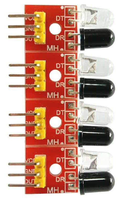
The IR Line Sensor Module (Manufacturer: Generic, Part ID: TCRT5000 IR Sensor Module) is a compact and efficient sensor designed to detect the presence of a line or path. It operates by emitting infrared (IR) light and measuring the reflected light intensity to distinguish between different surface contrasts. This makes it ideal for applications such as line-following robots, path navigation, and object detection.
Explore Projects Built with IR Line Sensor Module


Explore Projects Built with IR Line Sensor Module
Common Applications and Use Cases
- Line-following robots for automation and robotics competitions
- Path detection in autonomous vehicles
- Edge detection for conveyor belts
- Object detection in industrial automation
- Proximity sensing in robotics
Technical Specifications
The following table outlines the key technical details of the TCRT5000 IR Sensor Module:
| Parameter | Value |
|---|---|
| Operating Voltage | 3.3V to 5V |
| Operating Current | 10mA (typical) |
| Output Type | Digital (High/Low) |
| Detection Range | 2mm to 15mm (optimal: 2mm to 10mm) |
| IR Wavelength | 950nm |
| Dimensions | 32mm x 14mm x 7mm |
| Weight | ~3g |
Pin Configuration and Descriptions
The TCRT5000 IR Sensor Module has a 3-pin interface. The pinout is as follows:
| Pin | Name | Description |
|---|---|---|
| 1 | VCC | Power supply pin. Connect to 3.3V or 5V. |
| 2 | GND | Ground pin. Connect to the ground of the circuit. |
| 3 | OUT | Digital output pin. Outputs HIGH (1) when no line is detected, LOW (0) when a line is detected. |
Usage Instructions
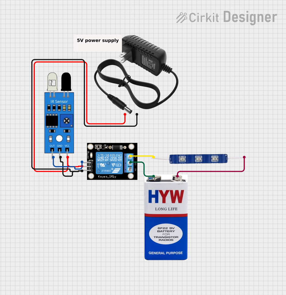
How to Use the Component in a Circuit
- Power the Module: Connect the
VCCpin to a 3.3V or 5V power source and theGNDpin to the ground of your circuit. - Connect the Output: Connect the
OUTpin to a digital input pin of your microcontroller (e.g., Arduino UNO). - Position the Sensor: Place the sensor module approximately 2mm to 10mm above the surface to be detected. Ensure the IR emitter and receiver face the surface.
- Calibrate the Sensor: Adjust the onboard potentiometer to fine-tune the sensitivity of the sensor for optimal performance.
Important Considerations and Best Practices
- Surface Contrast: The module works best when there is a high contrast between the line (e.g., black) and the background surface (e.g., white).
- Ambient Light: Avoid using the sensor in environments with strong ambient IR light, as it may interfere with detection.
- Distance: Maintain the recommended detection range (2mm to 10mm) for accurate results.
- Potentiometer Adjustment: Use the onboard potentiometer to adjust the sensitivity based on the surface and lighting conditions.
Example Code for Arduino UNO
The following code demonstrates how to use the TCRT5000 IR Sensor Module with an Arduino UNO to detect a line:
// Define the pin connected to the sensor's OUT pin
const int sensorPin = 2; // Digital pin 2
const int ledPin = 13;   // Built-in LED for visual feedback

void setup() {
  pinMode(sensorPin, INPUT); // Set sensor pin as input
  pinMode(ledPin, OUTPUT);   // Set LED pin as output
  Serial.begin(9600);        // Initialize serial communication
}

void loop() {
  int sensorValue = digitalRead(sensorPin); // Read the sensor output

  if (sensorValue == LOW) {
    // Line detected
    digitalWrite(ledPin, HIGH); // Turn on LED
    Serial.println("Line detected!");
  } else {
    // No line detected
    digitalWrite(ledPin, LOW);  // Turn off LED
    Serial.println("No line detected.");
  }

  delay(100); // Small delay for stability
}
Troubleshooting and FAQs
Common Issues and Solutions
Sensor Not Detecting the Line
- Cause: Incorrect positioning or insufficient contrast between the line and the surface.
- Solution: Ensure the sensor is within the recommended detection range (2mm to 10mm) and the line has a high contrast with the background.
False Positives or Unstable Output
- Cause: Ambient IR light interference or improper sensitivity adjustment.
- Solution: Reduce ambient IR light exposure and adjust the potentiometer to fine-tune the sensitivity.
No Output from the Sensor
- Cause: Incorrect wiring or insufficient power supply.
- Solution: Verify all connections and ensure the module is powered with 3.3V or 5V.
Output Always HIGH or LOW
- Cause: Faulty module or improper calibration.
- Solution: Test the module with a different microcontroller or replace the module if necessary.
FAQs
Q1: Can the TCRT5000 IR Sensor Module detect colors?
A1: No, the module detects contrast between surfaces but cannot differentiate specific colors.
Q2: Can I use this module with a 3.3V microcontroller?
A2: Yes, the module is compatible with both 3.3V and 5V systems.
Q3: How do I know if the sensor is working?
A3: The onboard LED will light up when the sensor detects a line. Additionally, you can monitor the digital output pin using a microcontroller.
Q4: Can I use multiple sensors for a line-following robot?
A4: Yes, you can use multiple TCRT5000 modules to detect multiple points along a line for better navigation.
By following this documentation, you can effectively integrate the TCRT5000 IR Sensor Module into your projects for reliable line detection and navigation.