How to Use 12v wireless relay (variant 2): Examples, Pinouts, and Specs
Introduction
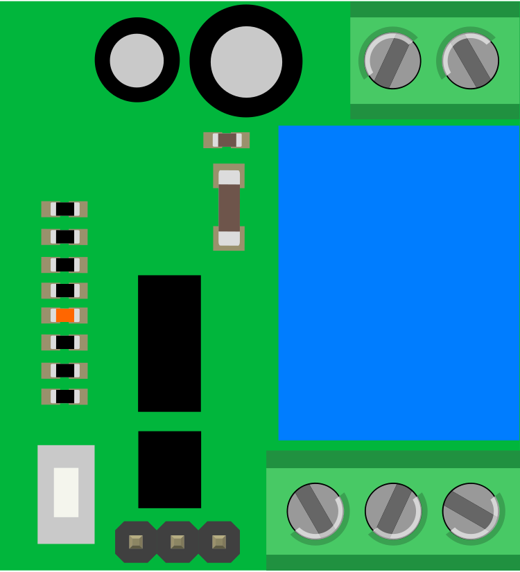
The 12V Wireless Relay (Variant 2) is a versatile electronic module designed to enable wireless control of electrical devices. Operating at 12 volts, this relay module eliminates the need for physical wiring between the control unit and the device being switched. It typically consists of a receiver and a transmitter, allowing users to remotely toggle devices on or off with ease.
Explore Projects Built with 12v wireless relay (variant 2)


Explore Projects Built with 12v wireless relay (variant 2)
Common Applications and Use Cases
- Home automation systems for controlling lights, fans, or appliances.
- Remote control of industrial equipment.
- Wireless switching in automotive applications.
- DIY projects requiring remote device control.
Technical Specifications
Key Technical Details
- Operating Voltage: 12V DC
- Relay Output Voltage: Supports up to 250V AC or 30V DC
- Relay Output Current: Up to 10A
- Communication Frequency: 433 MHz (typical, may vary by model)
- Control Distance: Up to 100 meters (line of sight, depending on environment)
- Trigger Mode: Momentary, toggle, or latching (configurable)
- Power Consumption: < 1W (standby)
Pin Configuration and Descriptions
Receiver Module
| Pin Name | Description |
|---|---|
| VCC | Power input (12V DC) |
| GND | Ground connection |
| NO | Normally Open terminal of the relay |
| COM | Common terminal of the relay |
| NC | Normally Closed terminal of the relay |
Transmitter Module
| Button | Function |
|---|---|
| Button A | Activates relay channel 1 |
| Button B | Activates relay channel 2 (if applicable) |
| Button C | Activates relay channel 3 (if applicable) |
| Button D | Activates relay channel 4 (if applicable) |
Usage Instructions
How to Use the Component in a Circuit
Power the Receiver Module:
- Connect the VCC pin to a 12V DC power source.
- Connect the GND pin to the ground of the power source.
Connect the Load:
- For devices that should be powered when the relay is activated, connect one terminal of the load to the NO (Normally Open) pin and the other terminal to the power source.
- For devices that should be powered when the relay is deactivated, connect one terminal of the load to the NC (Normally Closed) pin and the other terminal to the power source.
- The COM (Common) pin should be connected to the other side of the power source.
Pair the Transmitter and Receiver:
- Follow the pairing instructions provided with the module. Typically, this involves pressing a learning button on the receiver and then pressing a button on the transmitter.
Test the Setup:
- Press the corresponding button on the transmitter to toggle the relay and control the connected device.
Important Considerations and Best Practices
- Ensure the relay's voltage and current ratings are not exceeded to avoid damage.
- Use proper insulation and safety precautions when working with high-voltage AC loads.
- Avoid placing the receiver module in areas with significant RF interference to maintain reliable communication.
- If using multiple wireless relays, ensure they operate on different frequencies or have unique pairing codes to prevent interference.
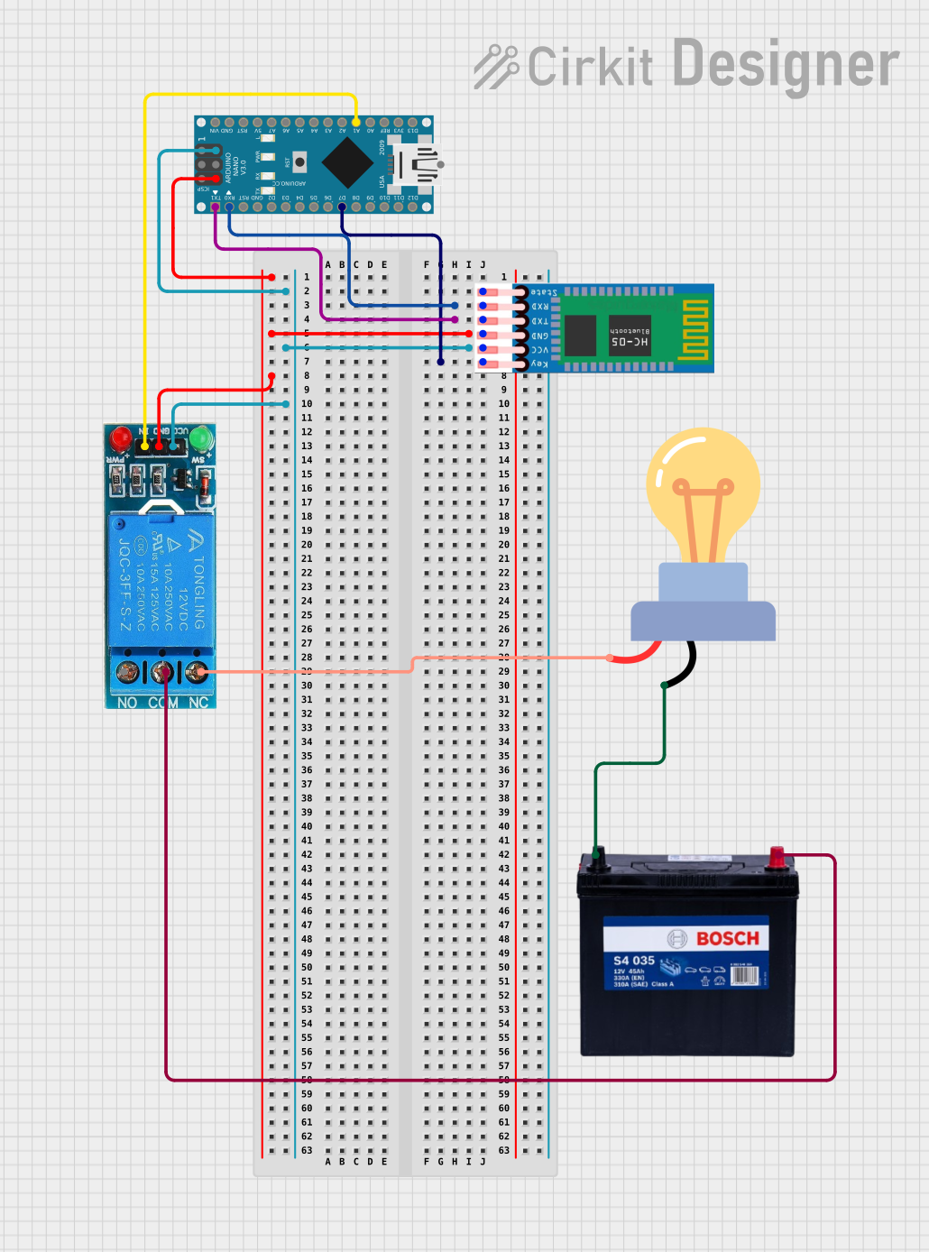
Example: Connecting to an Arduino UNO
The 12V Wireless Relay can be triggered by an Arduino UNO if the relay supports manual triggering via a digital pin. Below is an example code snippet:
// Example code to control a 12V wireless relay with an Arduino UNO
// Ensure the relay's input pin is connected to a digital pin on the Arduino

const int relayPin = 7; // Connect the relay's input pin to Arduino pin 7

void setup() {
  pinMode(relayPin, OUTPUT); // Set the relay pin as an output
  digitalWrite(relayPin, LOW); // Start with the relay off
}

void loop() {
  digitalWrite(relayPin, HIGH); // Turn the relay on
  delay(1000); // Keep it on for 1 second
  digitalWrite(relayPin, LOW); // Turn the relay off
  delay(1000); // Keep it off for 1 second
}
Note: This example assumes the relay module has a manual trigger input pin. If the relay is purely wireless, the Arduino cannot directly control it without additional hardware.
Troubleshooting and FAQs
Common Issues and Solutions
The relay does not respond to the transmitter:
- Ensure the receiver module is powered correctly (12V DC).
- Check the pairing between the transmitter and receiver. Re-pair if necessary.
- Verify that the transmitter's battery is not depleted.
The relay clicks but the connected device does not work:
- Confirm the wiring of the load to the relay's terminals (NO, NC, and COM).
- Ensure the load's voltage and current requirements are within the relay's specifications.
The control range is shorter than expected:
- Ensure there are no significant obstacles or RF interference between the transmitter and receiver.
- Replace the transmitter's battery if it is weak.
The relay remains stuck in one state:
- Check if the relay is configured for the correct trigger mode (momentary, toggle, or latching).
- Inspect the relay for physical damage or overheating.
FAQs
Can I use this relay with a 5V power source?
- No, the relay requires a 12V DC power source for proper operation.
What is the maximum load this relay can handle?
- The relay supports up to 250V AC or 30V DC with a maximum current of 10A.
Can I use multiple relays in the same area?
- Yes, but ensure they are paired with unique transmitters or operate on different frequencies to avoid interference.
Is this relay suitable for outdoor use?
- The module is not weatherproof. Use a protective enclosure if deploying outdoors.