How to Use USB Load Switch: Examples, Pinouts, and Specs

 Design with USB Load Switch in Cirkit Designer
Introduction
The TPS2024P is a USB load switch manufactured by Texas Instruments. It is designed to control power delivery to USB devices, offering features such as overcurrent protection, thermal shutdown, and controlled power switching. This component is ideal for applications requiring reliable power management and protection for USB ports.
Explore Projects Built with USB Load Switch

 Open Project in Cirkit Designer
 Open Project in Cirkit Designer
 Open Project in Cirkit Designer
 Open Project in Cirkit Designer
Explore Projects Built with USB Load Switch

 Open Project in Cirkit Designer
 Open Project in Cirkit Designer
 Open Project in Cirkit Designer
 Open Project in Cirkit Designer
Common Applications and Use Cases
- USB power distribution in consumer electronics
- Overcurrent protection for USB ports
- Power management in embedded systems
- Enabling/disabling USB power in portable devices
- Controlled power delivery in industrial systems
Technical Specifications
The TPS2024P is a robust and versatile USB load switch with the following key specifications:
Key Technical Details
- Input Voltage Range: 2.7V to 5.5V
- Continuous Output Current: 0.5A per channel (dual-channel device)
- Overcurrent Protection Threshold: 0.8A (typical)
- Quiescent Current: 0.5mA (typical)
- Enable Input Logic Levels:
- High: 2V (min)
- Low: 0.8V (max)
- Thermal Shutdown Protection: Yes
- Operating Temperature Range: -40°C to 85°C
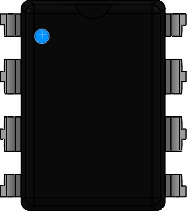
- Package Type: 8-pin PDIP (Plastic Dual In-line Package)
Pin Configuration and Descriptions
The TPS2024P is an 8-pin device with the following pinout:
| Pin Number | Pin Name | Description |
|---|---|---|
| 1 | IN1 | Power input for channel 1 |
| 2 | OUT1 | Power output for channel 1 |
| 3 | GND | Ground connection |
| 4 | EN1 | Enable input for channel 1 (active high) |
| 5 | EN2 | Enable input for channel 2 (active high) |
| 6 | OUT2 | Power output for channel 2 |
| 7 | IN2 | Power input for channel 2 |
| 8 | FAULT | Fault indicator output (active low, open-drain) |
Usage Instructions
How to Use the TPS2024P in a Circuit
- Power Supply: Connect a regulated power supply (2.7V to 5.5V) to the
IN1andIN2pins. Ensure the supply voltage matches the requirements of the connected USB devices. - Load Connection: Connect the USB device or load to the
OUT1andOUT2pins. - Enable Control: Use the
EN1andEN2pins to control the power delivery to each channel. Drive these pins high (≥2V) to enable the corresponding channel or low (≤0.8V) to disable it. - Fault Monitoring: Connect the
FAULTpin to a microcontroller or LED to monitor overcurrent or thermal shutdown events. The pin is active low and requires a pull-up resistor. - Bypass Capacitors: Place a 0.1µF ceramic capacitor close to each
INpin to stabilize the input voltage and reduce noise.
Important Considerations and Best Practices
- Thermal Management: Ensure adequate heat dissipation, especially when operating near the maximum current rating.
- Overcurrent Protection: The device automatically limits current to protect the load. Avoid connecting loads that exceed the overcurrent threshold.
- Fault Handling: Use the
FAULTpin to detect and respond to fault conditions in your system. - Decoupling Capacitors: Use decoupling capacitors on the input and output pins to minimize voltage fluctuations and improve stability.
Example: Connecting the TPS2024P to an Arduino UNO
The following example demonstrates how to use the TPS2024P to control power delivery to a USB device using an Arduino UNO.
Circuit Diagram
- Connect
IN1to the 5V pin of the Arduino. - Connect
OUT1to the USB device. - Connect
EN1to a digital output pin (e.g., D7) of the Arduino. - Connect the
FAULTpin to another digital input pin (e.g., D8) for fault monitoring.
Arduino Code
// Define pin connections
const int enablePin = 7;  // Pin connected to EN1
const int faultPin = 8;   // Pin connected to FAULT

void setup() {
  pinMode(enablePin, OUTPUT);  // Set EN1 as an output
  pinMode(faultPin, INPUT);    // Set FAULT as an input
  digitalWrite(enablePin, LOW); // Start with the load switch disabled
  Serial.begin(9600);          // Initialize serial communication
}

void loop() {
  // Enable the load switch
  digitalWrite(enablePin, HIGH);
  delay(1000);  // Wait for 1 second

  // Check for faults
  if (digitalRead(faultPin) == LOW) {
    Serial.println("Fault detected! Overcurrent or thermal shutdown.");
    digitalWrite(enablePin, LOW); // Disable the load switch
  } else {
    Serial.println("Load switch is operating normally.");
  }

  delay(1000);  // Wait for 1 second
}
Troubleshooting and FAQs
Common Issues and Solutions
No Power Output on
OUTPins:- Ensure the
ENpin is driven high (≥2V) to enable the channel. - Verify the input voltage is within the specified range (2.7V to 5.5V).
- Check for a fault condition by monitoring the
FAULTpin.
- Ensure the
Frequent Fault Conditions:
- Ensure the load current does not exceed the overcurrent protection threshold (0.8A).
- Verify proper heat dissipation to prevent thermal shutdown.
Noise or Voltage Fluctuations:
- Add decoupling capacitors (0.1µF) close to the
INandOUTpins. - Ensure the power supply is stable and free from excessive noise.
- Add decoupling capacitors (0.1µF) close to the
FAQs
Q1: Can the TPS2024P handle USB 3.0 devices?
A1: The TPS2024P is designed for USB 2.0 power requirements. It may not support the higher current demands of USB 3.0 devices.
Q2: What happens during an overcurrent event?
A2: The TPS2024P limits the current to protect the load and triggers the FAULT pin. The device may also enter thermal shutdown if the condition persists.
Q3: Can I use only one channel of the TPS2024P?
A3: Yes, you can use a single channel by leaving the unused channel's IN, OUT, and EN pins unconnected.
This concludes the documentation for the TPS2024P USB load switch.