How to Use UBX-M10050-KB MODULE: Examples, Pinouts, and Specs
Introduction
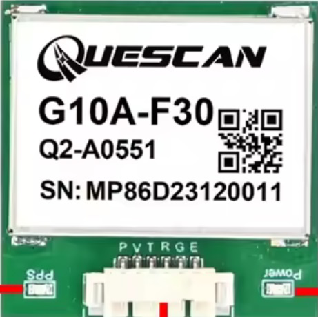
The UBX-M10050-KB is a compact GNSS (Global Navigation Satellite System) module designed for high-performance positioning applications. It supports multiple satellite systems, including GPS, GLONASS, and BeiDou, ensuring reliable and accurate location data. This module is ideal for applications requiring precise positioning, such as navigation systems, asset tracking, drones, and IoT devices.
Explore Projects Built with UBX-M10050-KB MODULE


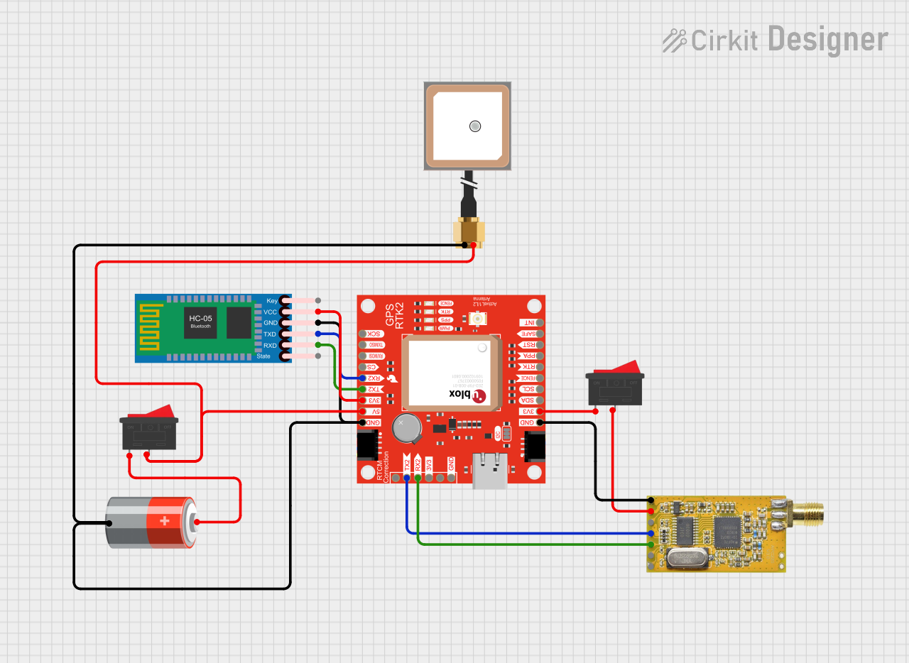
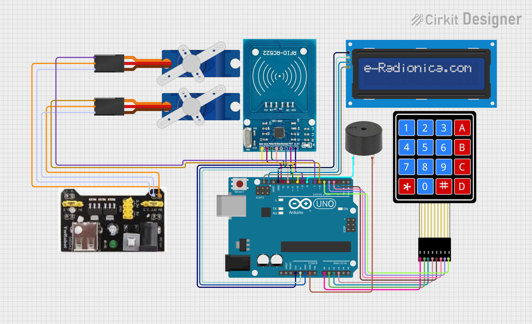
Explore Projects Built with UBX-M10050-KB MODULE
Common Applications and Use Cases
- Navigation systems for vehicles and drones
- Asset tracking in logistics and supply chain management
- IoT devices requiring geolocation capabilities
- Wearable devices with location-based features
- Surveying and mapping equipment
Technical Specifications
Key Technical Details
| Parameter | Value |
|---|---|
| GNSS Supported | GPS, GLONASS, BeiDou |
| Frequency Bands | L1 (1575.42 MHz for GPS) |
| Positioning Accuracy | < 2.5 meters CEP |
| Sensitivity | -167 dBm (tracking), -148 dBm (acquisition) |
| Supply Voltage | 2.7V to 3.6V |
| Power Consumption | 25 mA (typical) |
| Operating Temperature | -40°C to +85°C |
| Dimensions | 10.1 mm x 9.7 mm x 2.2 mm |
| Communication Interface | UART, I2C, SPI |
Pin Configuration and Descriptions
| Pin Number | Pin Name | Description |
|---|---|---|
| 1 | VCC | Power supply input (2.7V to 3.6V) |
| 2 | GND | Ground |
| 3 | TXD | UART Transmit |
| 4 | RXD | UART Receive |
| 5 | SDA | I2C Data Line |
| 6 | SCL | I2C Clock Line |
| 7 | SPI_MOSI | SPI Master Out Slave In |
| 8 | SPI_MISO | SPI Master In Slave Out |
| 9 | SPI_CLK | SPI Clock |
| 10 | SPI_CS | SPI Chip Select |
| 11 | RESET | Reset input (active low) |
| 12 | ANT_IN | Antenna input |
Usage Instructions
How to Use the UBX-M10050-KB in a Circuit
- Power Supply: Connect the VCC pin to a stable power source (2.7V to 3.6V) and the GND pin to ground.
- Antenna Connection: Attach an active or passive GNSS antenna to the ANT_IN pin for optimal signal reception.
- Communication Interface: Choose a communication protocol (UART, I2C, or SPI) and connect the corresponding pins to your microcontroller or host device.
- For UART: Use TXD and RXD pins.
- For I2C: Use SDA and SCL pins.
- For SPI: Use SPI_MOSI, SPI_MISO, SPI_CLK, and SPI_CS pins.
- Reset: Optionally connect the RESET pin to a microcontroller GPIO for manual or software-controlled resets.
Important Considerations and Best Practices
- Antenna Placement: Ensure the antenna has a clear view of the sky for optimal satellite reception.
- Power Supply: Use a low-noise power supply to avoid interference with GNSS signals.
- Decoupling Capacitors: Place decoupling capacitors close to the VCC pin to stabilize the power supply.
- Signal Integrity: Keep communication lines short and use proper shielding to minimize noise.
- Firmware Updates: Check for firmware updates from the manufacturer to ensure optimal performance.
Example: Connecting to an Arduino UNO
Below is an example of how to connect the UBX-M10050-KB module to an Arduino UNO using the UART interface.
Wiring
| UBX-M10050-KB Pin | Arduino UNO Pin |
|---|---|
| VCC | 3.3V |
| GND | GND |
| TXD | RX (Pin 0) |
| RXD | TX (Pin 1) |
| RESET | Digital Pin 7 |
Arduino Code
#include <SoftwareSerial.h>

// Define RX and TX pins for SoftwareSerial
SoftwareSerial GNSS(10, 11); // RX = Pin 10, TX = Pin 11

void setup() {
  Serial.begin(9600); // Initialize Serial Monitor
  GNSS.begin(9600);   // Initialize GNSS module communication

  Serial.println("UBX-M10050-KB GNSS Module Test");
}

void loop() {
  // Check if data is available from the GNSS module
  if (GNSS.available()) {
    // Read data from GNSS module and send it to Serial Monitor
    char c = GNSS.read();
    Serial.print(c);
  }

  // Optional: Send commands to the GNSS module
  if (Serial.available()) {
    char c = Serial.read();
    GNSS.write(c);
  }
}
Notes
- Use a logic level shifter if your Arduino operates at 5V logic levels, as the UBX-M10050-KB operates at 3.3V.
- Ensure the GNSS antenna is properly connected and positioned for accurate data.
Troubleshooting and FAQs
Common Issues and Solutions
No GNSS Fix or Poor Accuracy
- Cause: Obstructed antenna view or poor placement.
- Solution: Place the antenna in an open area with a clear view of the sky.
No Data Output from the Module
- Cause: Incorrect wiring or communication settings.
- Solution: Verify connections and ensure the baud rate matches the module's default (9600 bps).
Module Not Powering On
- Cause: Insufficient or unstable power supply.
- Solution: Check the power source and ensure it provides 2.7V to 3.6V.
Interference with GNSS Signals
- Cause: Nearby electronic devices causing RF interference.
- Solution: Relocate the module or shield it from interference sources.
FAQs
Q: Can the UBX-M10050-KB operate indoors?
A: While the module can operate indoors, signal reception may be weak or unavailable. Use it in open areas for best results.Q: Does the module support multiple GNSS systems simultaneously?
A: Yes, the module can track multiple satellite systems (GPS, GLONASS, BeiDou) simultaneously for improved accuracy.Q: How do I update the module's firmware?
A: Refer to the manufacturer's documentation for firmware update procedures and tools.Q: Can I use a passive antenna with this module?
A: Yes, but an active antenna is recommended for better performance.