How to Use Charge and discharge module: Examples, Pinouts, and Specs
Introduction
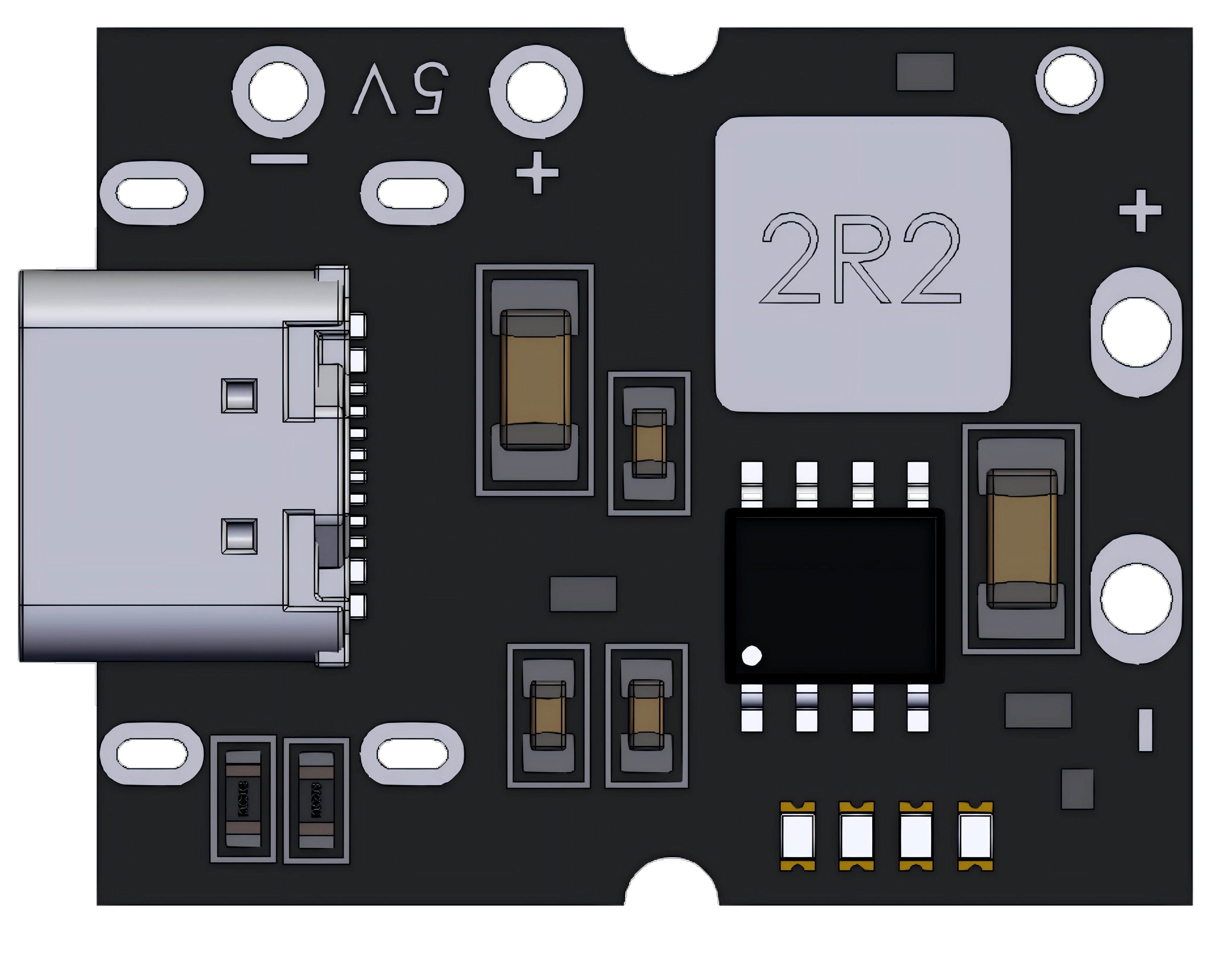
The Charge and Discharge Module is a versatile electronic component designed to manage the charging and discharging processes of batteries or capacitors. It ensures safe, efficient, and controlled energy storage and release, protecting the connected components from overcharging, over-discharging, or excessive current flow. This module is commonly used in power management systems, renewable energy setups, portable electronics, and battery-operated devices.
Explore Projects Built with Charge and discharge module


Explore Projects Built with Charge and discharge module
Common Applications:
- Battery charging and discharging circuits
- Energy storage systems (e.g., solar or wind energy setups)
- Power banks and portable chargers
- Capacitor-based energy storage and release systems
- Uninterruptible Power Supplies (UPS)
Technical Specifications
Below are the key technical details of the Charge and Discharge Module:
| Parameter | Value |
|---|---|
| Input Voltage Range | 5V to 30V |
| Output Voltage Range | 3.7V to 24V |
| Maximum Charging Current | 2A |
| Maximum Discharging Current | 3A |
| Efficiency | Up to 95% |
| Protection Features | Overcharge, Over-discharge, Short Circuit |
| Operating Temperature | -20°C to 60°C |
| Dimensions | 50mm x 25mm x 10mm |
Pin Configuration and Descriptions
The module typically has the following pin configuration:
| Pin Name | Description |
|---|---|
| VIN+ | Positive input terminal for the charging voltage source |
| VIN- | Negative input terminal for the charging voltage source |
| BAT+ | Positive terminal for connecting the battery or capacitor |
| BAT- | Negative terminal for connecting the battery or capacitor |
| LOAD+ | Positive terminal for connecting the load (device to be powered) |
| LOAD- | Negative terminal for connecting the load |
| EN | Enable pin to turn the module ON/OFF (active high) |
| STAT | Status pin to indicate charging/discharging status (e.g., LED connection) |
Usage Instructions
How to Use the Module in a Circuit
Connecting the Power Source:
- Connect the positive terminal of the power source (e.g., a DC adapter or solar panel) to the
VIN+pin. - Connect the negative terminal of the power source to the
VIN-pin.
- Connect the positive terminal of the power source (e.g., a DC adapter or solar panel) to the
Connecting the Battery or Capacitor:
- Attach the positive terminal of the battery or capacitor to the
BAT+pin. - Attach the negative terminal of the battery or capacitor to the
BAT-pin.
- Attach the positive terminal of the battery or capacitor to the
Connecting the Load:
- Connect the positive terminal of the load (e.g., a motor, LED, or microcontroller) to the
LOAD+pin. - Connect the negative terminal of the load to the
LOAD-pin.
- Connect the positive terminal of the load (e.g., a motor, LED, or microcontroller) to the
Enable the Module:
- If the module has an
ENpin, ensure it is connected to a HIGH signal (e.g., 3.3V or 5V) to enable the module.
- If the module has an
Monitor the Status:
- Use the
STATpin to connect an LED or microcontroller to monitor the charging/discharging status.
- Use the
Important Considerations and Best Practices
- Ensure the input voltage is within the specified range (5V to 30V) to avoid damaging the module.
- Do not exceed the maximum charging or discharging current ratings (2A and 3A, respectively).
- Use appropriate heat dissipation methods (e.g., heatsinks) if the module operates at high currents for extended periods.
- For battery applications, ensure the battery type (e.g., Li-ion, LiPo) is compatible with the module's charging profile.
- If using with an Arduino UNO or similar microcontroller, ensure proper grounding between the module and the microcontroller.
Example Code for Arduino UNO
Below is an example of how to monitor the charging status using the STAT pin with an Arduino UNO:
// Define the STAT pin connected to the module
const int statPin = 7; // Connect STAT pin to Arduino digital pin 7

void setup() {
  pinMode(statPin, INPUT); // Set STAT pin as input
  Serial.begin(9600);      // Initialize serial communication
}

void loop() {
  int status = digitalRead(statPin); // Read the status pin

  if (status == HIGH) {
    Serial.println("Charging in progress...");
    // If STAT pin is HIGH, charging is active
  } else {
    Serial.println("Charging complete or idle.");
    // If STAT pin is LOW, charging is complete or no activity
  }

  delay(1000); // Wait for 1 second before checking again
}
Troubleshooting and FAQs
Common Issues and Solutions
Module Not Powering On:
- Cause: Insufficient input voltage or incorrect wiring.
- Solution: Verify the input voltage is within the specified range (5V to 30V) and check all connections.
Battery Not Charging:
- Cause: Battery polarity is reversed or battery is incompatible.
- Solution: Ensure the battery is connected with the correct polarity and is compatible with the module.
Load Not Receiving Power:
- Cause: Load current exceeds the module's maximum discharging current.
- Solution: Use a load that draws less than 3A or use a higher-rated module.
Overheating:
- Cause: Prolonged operation at high currents without proper cooling.
- Solution: Add a heatsink or cooling fan to dissipate heat effectively.
STAT Pin Not Responding:
- Cause: Faulty connection or incorrect pin configuration in the microcontroller.
- Solution: Check the wiring and ensure the correct pin is defined in the code.
FAQs
Q1: Can this module charge multiple batteries in series?
A1: No, this module is designed for single-cell batteries or capacitors. For multiple batteries, use a dedicated battery management system (BMS).
Q2: Can I use this module with a solar panel?
A2: Yes, as long as the solar panel's output voltage and current are within the module's input range.
Q3: What happens if the input voltage exceeds 30V?
A3: Exceeding the input voltage may permanently damage the module. Always use a regulated power source.
Q4: Can I use this module to charge supercapacitors?
A4: Yes, but ensure the supercapacitor's voltage and current ratings are compatible with the module.
Q5: Is the module compatible with LiFePO4 batteries?
A5: Compatibility depends on the module's charging profile. Check the datasheet or consult the manufacturer for details.