
How to Use ADXL345: Examples, Pinouts, and Specs
 Design with ADXL345 in Cirkit Designer
Introduction
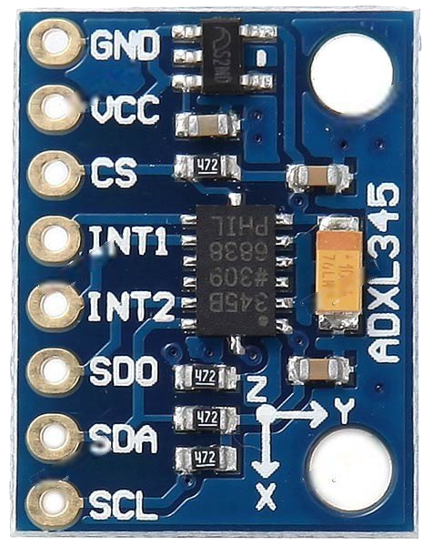
The ADXL345 is a small, thin, low-power, 3-axis accelerometer with a digital output, manufactured by Adafruit (Part ID: ADXL345). It is designed to measure acceleration in three dimensions (X, Y, and Z axes) and is widely used in applications such as mobile devices, gaming, motion detection, and tilt sensing. With its high resolution (13-bit) and low power consumption, the ADXL345 is ideal for applications requiring precise motion tracking and orientation sensing.
Explore Projects Built with ADXL345
 Open Project in Cirkit Designer
 Open Project in Cirkit Designer
 Open Project in Cirkit Designer
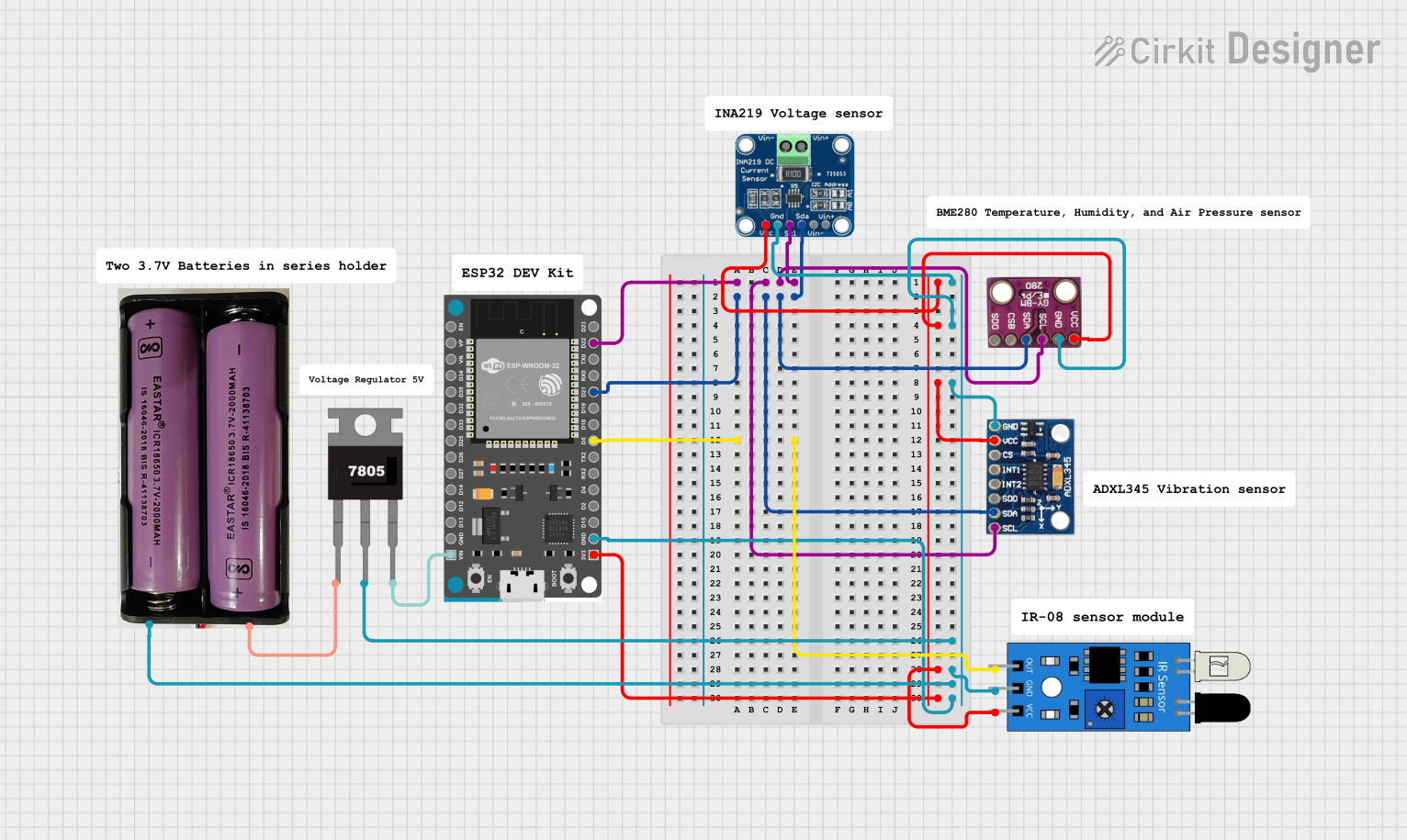 Open Project in Cirkit Designer
Explore Projects Built with ADXL345
Open Project in Cirkit DesignerOpen Project in Cirkit DesignerOpen Project in Cirkit DesignerOpen Project in Cirkit DesignerCommon Applications
- Mobile device orientation and motion sensing
- Gaming controllers and motion-based input devices
- Wearable fitness trackers and pedometers
- Robotics and drone stabilization
- Vibration monitoring and tilt sensing
Technical Specifications
The ADXL345 offers a range of features and specifications that make it versatile and easy to integrate into various projects.
Key Technical Details
| Parameter | Value |
|---|---|
| Supply Voltage | 2.0V to 3.6V |
| Operating Current | 40 µA (measurement mode), 0.1 µA (standby) |
| Measurement Range | ±2g, ±4g, ±8g, ±16g (selectable) |
| Resolution | 13-bit (4 mg/LSB at ±2g) |
| Communication Interface | I2C or SPI |
| Data Rate | 0.1 Hz to 3200 Hz |
| Operating Temperature Range | -40°C to +85°C |
| Dimensions | 3 mm × 5 mm × 1 mm |
Pin Configuration and Descriptions
The ADXL345 breakout board from Adafruit typically includes the following pins:
| Pin Name | Pin Type | Description |
|---|---|---|
| VIN | Power | Input voltage (2.0V to 3.6V). Connect to the power supply. |
| GND | Ground | Ground connection. |
| SDA | Data Line | I2C data line. Connect to the microcontroller's SDA pin. |
| SCL | Clock Line | I2C clock line. Connect to the microcontroller's SCL pin. |
| CS | Chip Select | Used for SPI communication. Pull low to enable SPI mode. |
| SDO | Data Out | SPI data output. Can also be used to set the I2C address (high or low). |
| INT1 | Interrupt | Interrupt pin 1 for motion detection or data-ready signals. |
| INT2 | Interrupt | Interrupt pin 2 for additional interrupt configurations. |
Usage Instructions
The ADXL345 can be used in either I2C or SPI communication mode, depending on your project requirements. Below are the steps to integrate the ADXL345 into a circuit and use it with an Arduino UNO.
Connecting the ADXL345 to an Arduino UNO (I2C Mode)
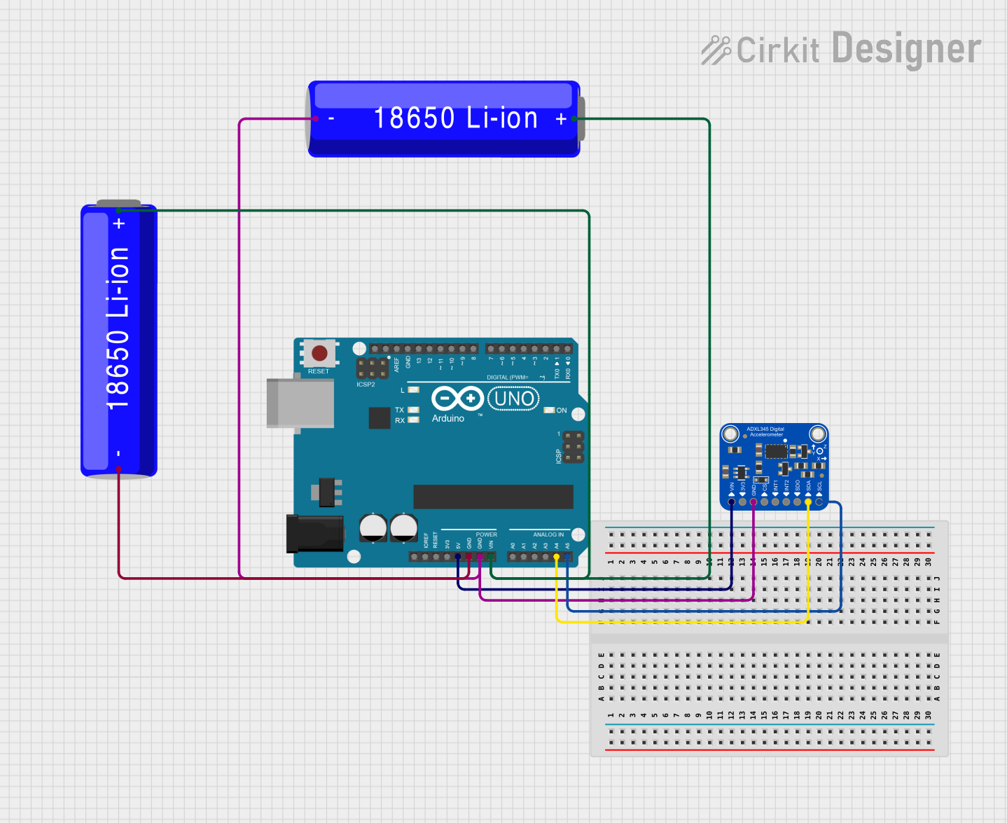
- Connect the VIN pin of the ADXL345 to the 3.3V pin on the Arduino UNO.
- Connect the GND pin of the ADXL345 to the GND pin on the Arduino UNO.
- Connect the SDA pin of the ADXL345 to the A4 pin on the Arduino UNO (I2C data line).
- Connect the SCL pin of the ADXL345 to the A5 pin on the Arduino UNO (I2C clock line).
- Leave the CS pin unconnected (default mode is I2C).
Arduino Code Example
Below is an example Arduino sketch to read acceleration data from the ADXL345 using the Adafruit ADXL345 library.
#include <Wire.h>
#include <Adafruit_Sensor.h>
#include <Adafruit_ADXL345_U.h>

// Create an ADXL345 object
Adafruit_ADXL345_Unified accel = Adafruit_ADXL345_Unified(12345);

void setup() {
  Serial.begin(9600);
  // Initialize the ADXL345 sensor
  if (!accel.begin()) {
    Serial.println("Failed to find ADXL345 chip. Check connections.");
    while (1); // Halt the program if the sensor is not detected
  }
  Serial.println("ADXL345 initialized successfully!");

  // Set the range to ±4g (other options: ±2g, ±8g, ±16g)
  accel.setRange(ADXL345_RANGE_4_G);
  Serial.println("Range set to ±4g.");
}

void loop() {
  sensors_event_t event;
  accel.getEvent(&event);

  // Print acceleration data for X, Y, and Z axes
  Serial.print("X: "); Serial.print(event.acceleration.x); Serial.print(" m/s^2 ");
  Serial.print("Y: "); Serial.print(event.acceleration.y); Serial.print(" m/s^2 ");
  Serial.print("Z: "); Serial.print(event.acceleration.z); Serial.println(" m/s^2");

  delay(500); // Delay for readability
}
Important Considerations
- Ensure the ADXL345 is powered with a voltage within its operating range (2.0V to 3.6V).
- Use appropriate pull-up resistors (typically 4.7kΩ) on the SDA and SCL lines if they are not already included on the breakout board.
- When using SPI mode, configure the CS pin and ensure proper connections for SDO and SCL.
- Avoid exposing the sensor to extreme temperatures or mechanical stress.
Troubleshooting and FAQs
Common Issues
The sensor is not detected by the Arduino.
- Ensure the wiring is correct and matches the I2C configuration.
- Verify that the I2C address (default: 0x53) is not conflicting with other devices on the bus.
- Check for loose connections or damaged wires.
Incorrect or unstable acceleration readings.
- Verify that the sensor is securely mounted and not subject to vibrations.
- Ensure the power supply is stable and within the specified range.
- Check the range setting and ensure it matches your application's requirements.
Interrupts are not triggering as expected.
- Double-check the interrupt configuration in your code.
- Ensure the INT1 or INT2 pins are properly connected to the microcontroller.
FAQs
Q: Can the ADXL345 measure tilt angles?
A: Yes, the ADXL345 can measure tilt angles by calculating the arctangent of the acceleration values on the X, Y, and Z axes.
Q: What is the maximum sampling rate of the ADXL345?
A: The ADXL345 supports a maximum data rate of 3200 Hz.
Q: Can I use the ADXL345 with a 5V microcontroller?
A: Yes, but you must use a logic level shifter or ensure the breakout board includes level-shifting circuitry to protect the sensor.
Q: How do I change the I2C address of the ADXL345?
A: The I2C address can be changed by connecting the SDO pin to either GND (0x53) or VCC (0x1D).
By following this documentation, you can successfully integrate and use the ADXL345 in your projects!