Cirkit Designer Logo
Cirkit Designer
Your all-in-one circuit design IDE
Home / 
Component Documentation

How to Use ISD1820: Examples, Pinouts, and Specs

Image of ISD1820
Cirkit Designer LogoDesign with ISD1820 in Cirkit Designer

Introduction

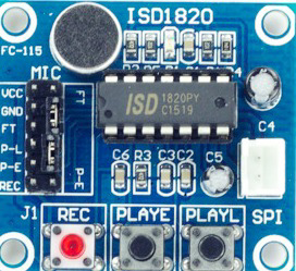
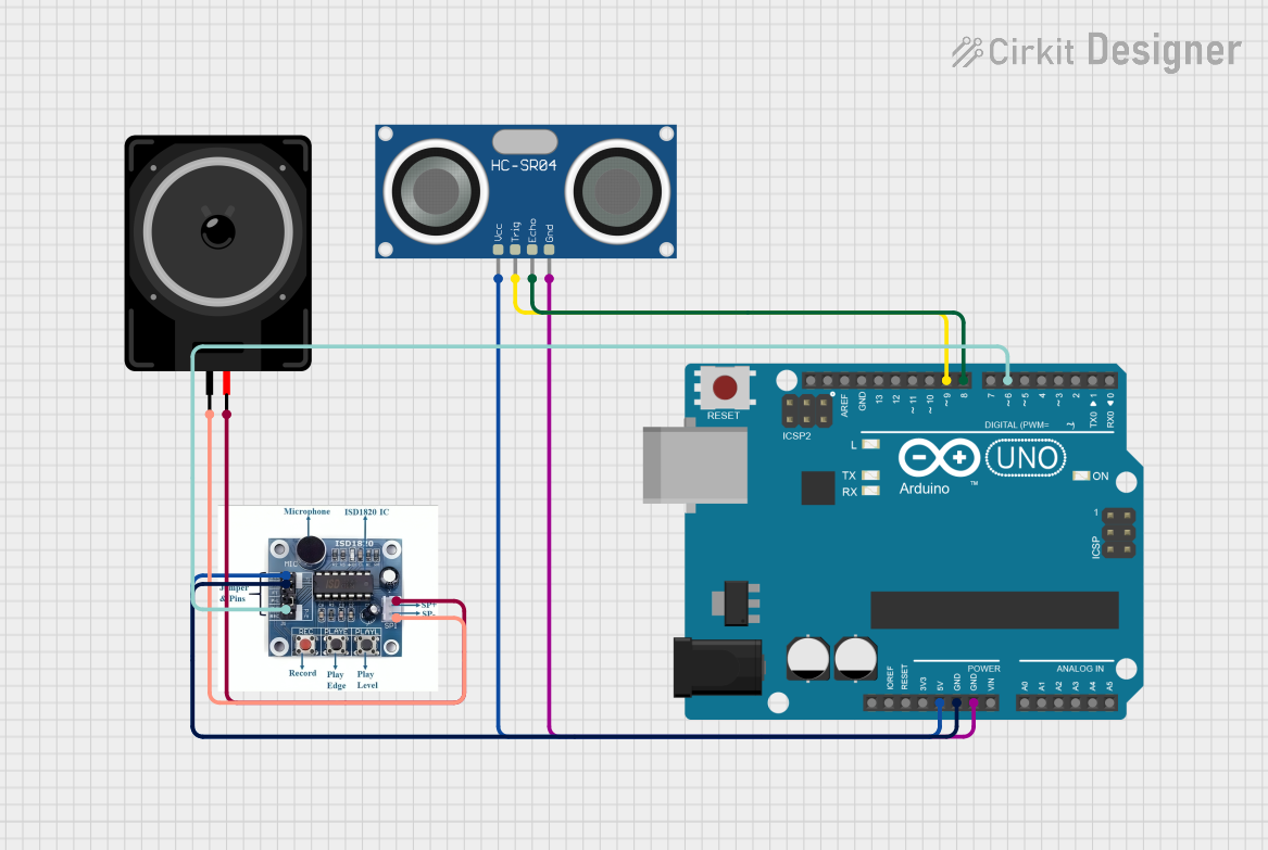
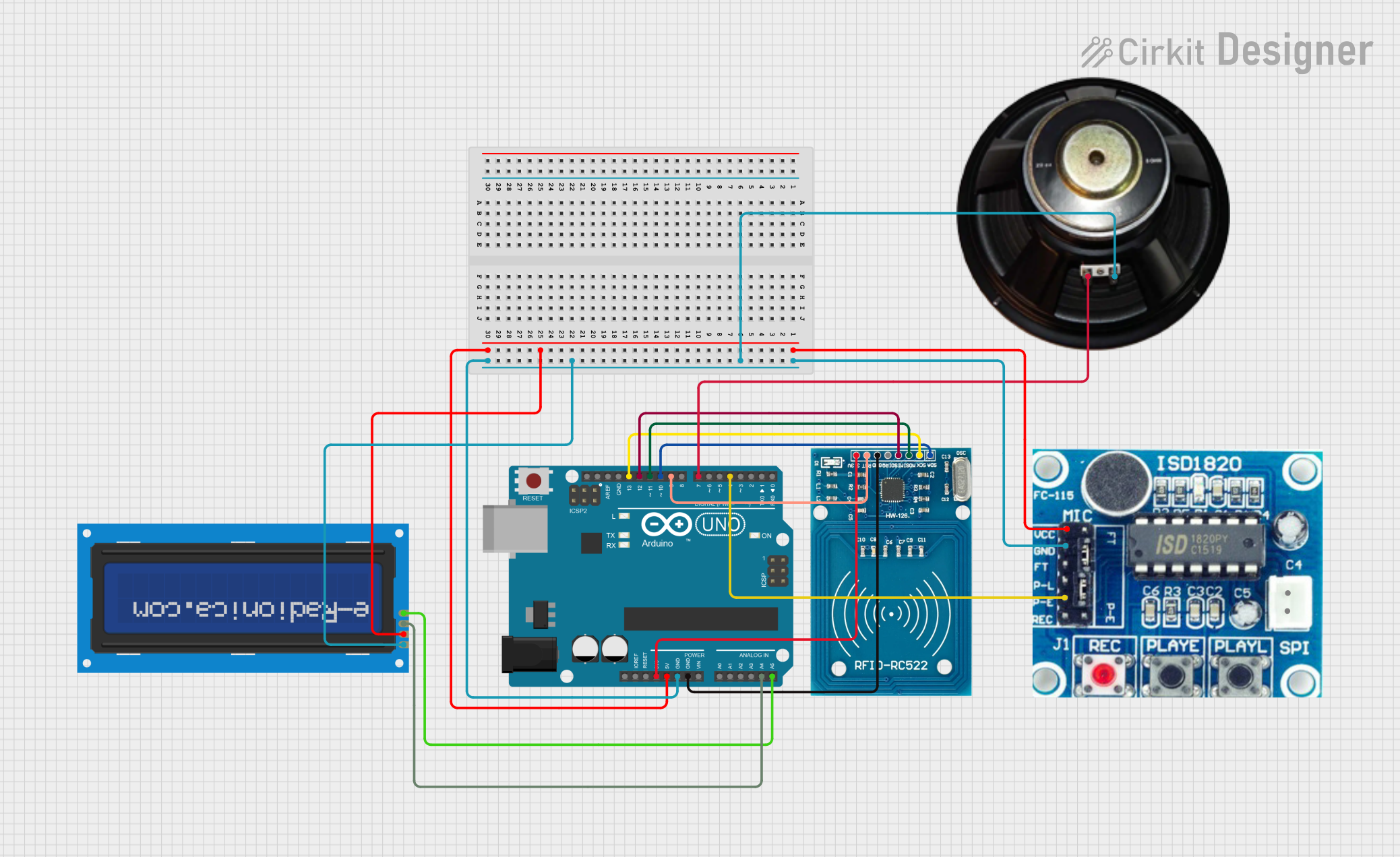
The ISD1820 is a highly integrated, high-quality, single-chip voice recording and playback device ideally suited for a variety of electronic systems. The module can record up to 20 seconds of audio data, which can be played back through a built-in audio amplifier and speaker output. Common applications include voice memos, talking toys, alarm systems, and automated response systems.

Explore Projects Built with ISD1820

Use Cirkit Designer to design, explore, and prototype these projects online. Some projects support real-time simulation. Click "Open Project" to start designing instantly!
Arduino UNO Based Ultrasonic Distance Measurement with Voice Playback
Image of sound playback: A project utilizing ISD1820 in a practical application
This circuit features an Arduino UNO microcontroller interfaced with an ISD 1820 voice recording and playback module and an HC-SR04 ultrasonic sensor. The Arduino controls the playback of the ISD 1820 module and reads distance measurements from the HC-SR04 sensor. The ISD 1820 is connected to a loudspeaker for audio output, and the ultrasonic sensor is used for triggering playback based on proximity detection.
Cirkit Designer LogoOpen Project in Cirkit Designer
ESP32 and MCP23017-Based Smart Relay Control System with DHT22 Sensors
Image of Indoor Lounge: A project utilizing ISD1820 in a practical application
This circuit is a control system that uses an ESP32 microcontroller to manage multiple relays and read data from DHT22 temperature and humidity sensors. The DFRobot Gravity MCP23017 I2C module expands the GPIO capabilities of the ESP32, allowing it to control additional relays for switching high-power devices.
Cirkit Designer LogoOpen Project in Cirkit Designer
Arduino UNO RFID Access Control with Voice Feedback and LCD Display
Image of smart bus station: A project utilizing ISD1820 in a practical application
This circuit is designed to read RFID tags, provide audio playback through a speaker, and display information on an LCD screen. The Arduino UNO serves as the central controller, interfacing with the RFID-RC522 module via SPI, triggering the ISD1820 voice module, and communicating with the LCD using I2C. It is suitable for applications such as access control systems with user feedback.
Cirkit Designer LogoOpen Project in Cirkit Designer
ESP8266 Multi-Tool with RFID, IR, RF, and Wi-Fi Control
Image of clipper 1: A project utilizing ISD1820 in a practical application
This circuit is a multi-functional tool based on the ESP-8266 microcontroller, integrating RFID, IR, RF, and Wi-Fi capabilities. It includes an RFID reader, IR transmitter and receiver, RF module, SD card module, and an I2C LCD for user interaction, with pushbuttons for navigation and control.
Cirkit Designer LogoOpen Project in Cirkit Designer

Explore Projects Built with ISD1820

Use Cirkit Designer to design, explore, and prototype these projects online. Some projects support real-time simulation. Click "Open Project" to start designing instantly!
Image of sound playback: A project utilizing ISD1820 in a practical application
Arduino UNO Based Ultrasonic Distance Measurement with Voice Playback
This circuit features an Arduino UNO microcontroller interfaced with an ISD 1820 voice recording and playback module and an HC-SR04 ultrasonic sensor. The Arduino controls the playback of the ISD 1820 module and reads distance measurements from the HC-SR04 sensor. The ISD 1820 is connected to a loudspeaker for audio output, and the ultrasonic sensor is used for triggering playback based on proximity detection.
Cirkit Designer LogoOpen Project in Cirkit Designer
Image of Indoor Lounge: A project utilizing ISD1820 in a practical application
ESP32 and MCP23017-Based Smart Relay Control System with DHT22 Sensors
This circuit is a control system that uses an ESP32 microcontroller to manage multiple relays and read data from DHT22 temperature and humidity sensors. The DFRobot Gravity MCP23017 I2C module expands the GPIO capabilities of the ESP32, allowing it to control additional relays for switching high-power devices.
Cirkit Designer LogoOpen Project in Cirkit Designer
Image of smart bus station: A project utilizing ISD1820 in a practical application
Arduino UNO RFID Access Control with Voice Feedback and LCD Display
This circuit is designed to read RFID tags, provide audio playback through a speaker, and display information on an LCD screen. The Arduino UNO serves as the central controller, interfacing with the RFID-RC522 module via SPI, triggering the ISD1820 voice module, and communicating with the LCD using I2C. It is suitable for applications such as access control systems with user feedback.
Cirkit Designer LogoOpen Project in Cirkit Designer
Image of clipper 1: A project utilizing ISD1820 in a practical application
ESP8266 Multi-Tool with RFID, IR, RF, and Wi-Fi Control
This circuit is a multi-functional tool based on the ESP-8266 microcontroller, integrating RFID, IR, RF, and Wi-Fi capabilities. It includes an RFID reader, IR transmitter and receiver, RF module, SD card module, and an I2C LCD for user interaction, with pushbuttons for navigation and control.
Cirkit Designer LogoOpen Project in Cirkit Designer

Technical Specifications

Key Technical Details

  • Operating Voltage: 2.4V to 5.5V
  • Recording Time: 8 to 20 seconds (adjustable quality)
  • Sampling Rate: 3.2 kHz to 8 kHz
  • Speaker Output: 8Ω, typically 0.5W
  • Microphone: Onboard electret microphone
  • Current Consumption: 25 mA (typical during playback)

Pin Configuration and Descriptions

Pin Number Pin Name Description
1 VCC Power supply (2.4V to 5.5V)
2 GND Ground
3 REC Record button input (active low)
4 PLAYE Edge-activated play button input (active low)
5 PLAYL Level-activated play button input (active low)
6 SP+ Speaker positive output
7 SP- Speaker negative output
8 FT Feed-through mode enable (active low)
9 P-E Playback end output (active low)
10 ANA OUT Analog output (for external amplifiers)
11 ANA IN Analog input (for external audio sources)
12 MIC_REF Microphone bias reference voltage
13 AGC Automatic gain control for microphone input
14 VCC Power supply (2.4V to 5.5V)

Usage Instructions

How to Use the ISD1820 in a Circuit

  1. Powering the Module:

    • Connect the VCC pin to a 2.4V to 5.5V power source.
    • Connect the GND pin to the ground of the power source.
  2. Recording Audio:

    • Press and hold the REC pin to ground to start recording.
    • Release the REC pin to stop recording.
  3. Playback Audio:

    • Briefly connect the PLAYE pin to ground to play the entire message once.
    • Connect the PLAYL pin to ground to play the message repeatedly until the pin is released.
  4. Connecting a Speaker:

    • Connect the speaker's positive terminal to the SP+ pin.
    • Connect the speaker's negative terminal to the SP- pin.

Important Considerations and Best Practices

  • Ensure that the power supply voltage does not exceed 5.5V to prevent damage to the module.
  • Keep the recording and playback volume at a moderate level to avoid distortion.
  • Place the microphone away from the speaker to prevent feedback.
  • Use a shielded cable if extending the microphone or speaker wires to reduce noise.

Troubleshooting and FAQs

Common Issues

  • No Sound During Playback:

    • Check the speaker connections.
    • Ensure that the power supply is within the specified range.
    • Verify that a recording has been made.
  • Low Recording Quality:

    • Adjust the distance from the microphone during recording.
    • Reduce background noise when recording.
  • Playback Starts Automatically:

    • Ensure that the PLAYL pin is not unintentionally grounded.

Solutions and Tips for Troubleshooting

  • If the module is not functioning, double-check all connections and ensure that the power supply is stable and within the specified range.
  • For better audio quality, consider using an external amplifier connected to the ANA OUT pin.
  • If the playback volume is too low, check the speaker's impedance and power rating. Use an 8Ω, 0.5W speaker for optimal performance.

FAQs

Q: Can I extend the recording time beyond 20 seconds? A: The recording time is fixed based on the internal memory of the ISD1820. To achieve longer recording times, consider using an external memory chip or a different model with a larger memory capacity.

Q: How can I erase a recording? A: To erase a recording, simply record a new message over the previous one. There is no separate erase function.

Q: Can I use the ISD1820 with an Arduino? A: Yes, the ISD1820 can be easily interfaced with an Arduino for more complex control over recording and playback functions.

Example Arduino Code

// Define ISD1820 pin connections
const int recPin = 2;   // REC connected to digital pin 2
const int playPin = 3;  // PLAYE connected to digital pin 3

void setup() {
  pinMode(recPin, OUTPUT);
  pinMode(playPin, OUTPUT);
  // Start with both pins high (inactive)
  digitalWrite(recPin, HIGH);
  digitalWrite(playPin, HIGH);
}

void loop() {
  // Record for 5 seconds
  digitalWrite(recPin, LOW);  // Start recording
  delay(5000);                // Record for 5 seconds
  digitalWrite(recPin, HIGH); // Stop recording

  delay(1000); // Wait for 1 second

  // Playback the recorded message
  digitalWrite(playPin, LOW); // Start playback
  delay(100);                 // Short delay
  digitalWrite(playPin, HIGH); // Stop playback

  delay(5000); // Wait for 5 seconds before next loop
}

Note: The above code is a simple example to demonstrate recording and playback using an Arduino. In a practical application, you would typically use buttons or sensors to trigger these actions.