Cirkit Designer Logo
Cirkit Designer
Your all-in-one circuit design IDE
Home / 
Component Documentation

How to Use Controlador de Relé 8 Canais 5V RS485 Modbus RTU RS232 TTL: Examples, Pinouts, and Specs

Image of Controlador de Relé 8 Canais 5V RS485 Modbus RTU RS232 TTL
Cirkit Designer LogoDesign with Controlador de Relé 8 Canais 5V RS485 Modbus RTU RS232 TTL in Cirkit Designer

Introduction

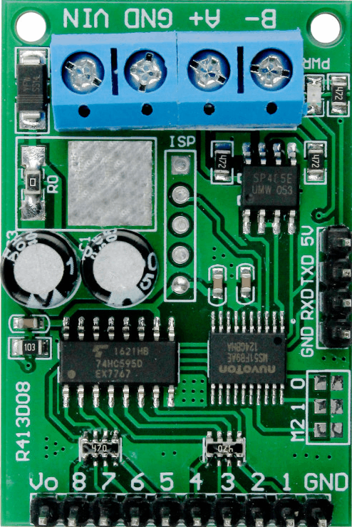
The Controlador de Relé 8 Canais 5V RS485 Modbus RTU RS232 TTL is a versatile relay module designed for industrial and home automation applications. It features 8 independent relay channels, allowing users to control multiple devices such as lights, motors, and other electrical equipment. The module supports communication via RS485 (Modbus RTU protocol) and RS232 TTL, making it suitable for integration with microcontrollers, PLCs, and other control systems.

Explore Projects Built with Controlador de Relé 8 Canais 5V RS485 Modbus RTU RS232 TTL

Use Cirkit Designer to design, explore, and prototype these projects online. Some projects support real-time simulation. Click "Open Project" to start designing instantly!
Arduino UNO and Relay-Controlled RS485 Communication System
Image of Diagrama: A project utilizing Controlador de Relé 8 Canais 5V RS485 Modbus RTU RS232 TTL in a practical application
This circuit features an Arduino UNO microcontroller interfaced with a 4-channel relay module and a UART TTL to RS485 converter. The Arduino controls the relays via digital pins and communicates with the RS485 converter for serial communication, enabling control of external devices and communication over long distances.
Cirkit Designer LogoOpen Project in Cirkit Designer
ESP32-Based Smart Energy Monitoring System with RS485 Communication
Image of Project 1: A project utilizing Controlador de Relé 8 Canais 5V RS485 Modbus RTU RS232 TTL in a practical application
This circuit features an ESP32 microcontroller interfaced with an RS485 communication module, a current sensor (ACS712), a voltage sensor (ZMPT101B), and a 1-channel relay. The ESP32 collects current and voltage data from the sensors, controls the relay, and communicates with other devices via the RS485 module.
Cirkit Designer LogoOpen Project in Cirkit Designer
Wi-Fi Controlled Smart Relay Switch with ESP8266 and MCP23017
Image of Bed Room: A project utilizing Controlador de Relé 8 Canais 5V RS485 Modbus RTU RS232 TTL in a practical application
This circuit is designed to control an 8-channel relay module via an ESP8266 microcontroller, which interfaces with an MCP23017 I/O expander over I2C. The ESP8266 connects to a WiFi network and subscribes to MQTT topics to receive commands for toggling the relays. Additionally, there are toggle switches connected to the MCP23017 that allow manual control of the relays, with the system's state being reported back via MQTT.
Cirkit Designer LogoOpen Project in Cirkit Designer
ESP32-Powered 8-Channel Relay Controller with Wi-Fi Connectivity
Image of Olimex ESP32-POE2 4Ch X 2 Switches: A project utilizing Controlador de Relé 8 Canais 5V RS485 Modbus RTU RS232 TTL in a practical application
This circuit features an ESP32 microcontroller connected to an 8-channel relay module. The ESP32 controls the relay channels via its GPIO pins, allowing for the switching of external devices or loads through the relays.
Cirkit Designer LogoOpen Project in Cirkit Designer

Explore Projects Built with Controlador de Relé 8 Canais 5V RS485 Modbus RTU RS232 TTL

Use Cirkit Designer to design, explore, and prototype these projects online. Some projects support real-time simulation. Click "Open Project" to start designing instantly!
Image of Diagrama: A project utilizing Controlador de Relé 8 Canais 5V RS485 Modbus RTU RS232 TTL in a practical application
Arduino UNO and Relay-Controlled RS485 Communication System
This circuit features an Arduino UNO microcontroller interfaced with a 4-channel relay module and a UART TTL to RS485 converter. The Arduino controls the relays via digital pins and communicates with the RS485 converter for serial communication, enabling control of external devices and communication over long distances.
Cirkit Designer LogoOpen Project in Cirkit Designer
Image of Project 1: A project utilizing Controlador de Relé 8 Canais 5V RS485 Modbus RTU RS232 TTL in a practical application
ESP32-Based Smart Energy Monitoring System with RS485 Communication
This circuit features an ESP32 microcontroller interfaced with an RS485 communication module, a current sensor (ACS712), a voltage sensor (ZMPT101B), and a 1-channel relay. The ESP32 collects current and voltage data from the sensors, controls the relay, and communicates with other devices via the RS485 module.
Cirkit Designer LogoOpen Project in Cirkit Designer
Image of Bed Room: A project utilizing Controlador de Relé 8 Canais 5V RS485 Modbus RTU RS232 TTL in a practical application
Wi-Fi Controlled Smart Relay Switch with ESP8266 and MCP23017
This circuit is designed to control an 8-channel relay module via an ESP8266 microcontroller, which interfaces with an MCP23017 I/O expander over I2C. The ESP8266 connects to a WiFi network and subscribes to MQTT topics to receive commands for toggling the relays. Additionally, there are toggle switches connected to the MCP23017 that allow manual control of the relays, with the system's state being reported back via MQTT.
Cirkit Designer LogoOpen Project in Cirkit Designer
Image of Olimex ESP32-POE2 4Ch X 2 Switches: A project utilizing Controlador de Relé 8 Canais 5V RS485 Modbus RTU RS232 TTL in a practical application
ESP32-Powered 8-Channel Relay Controller with Wi-Fi Connectivity
This circuit features an ESP32 microcontroller connected to an 8-channel relay module. The ESP32 controls the relay channels via its GPIO pins, allowing for the switching of external devices or loads through the relays.
Cirkit Designer LogoOpen Project in Cirkit Designer

Common Applications

  • Industrial automation systems
  • Smart home projects
  • Remote device control via RS485 or RS232
  • Motor and lighting control
  • IoT (Internet of Things) applications

Technical Specifications

Key Technical Details

Parameter Specification
Operating Voltage 5V DC
Communication Interfaces RS485 (Modbus RTU), RS232 TTL
Number of Relays 8
Relay Type SPDT (Single Pole Double Throw)
Relay Voltage Rating 250V AC / 30V DC
Relay Current Rating 10A
Baud Rate (RS485/RS232) Configurable (default: 9600 bps)
Isolation Optocoupler isolation for each relay
Dimensions 135mm x 55mm x 20mm
Operating Temperature -40°C to 85°C

Pin Configuration and Descriptions

Power and Communication Pins

Pin Name Description
VCC 5V DC power input
GND Ground connection
A (RS485) RS485 communication line (A)
B (RS485) RS485 communication line (B)
TXD RS232 TTL transmit pin
RXD RS232 TTL receive pin

Relay Output Terminals

Terminal Group Description
COMx Common terminal for relay channel x
NOx Normally open terminal for relay channel x
NCx Normally closed terminal for relay channel x

Usage Instructions

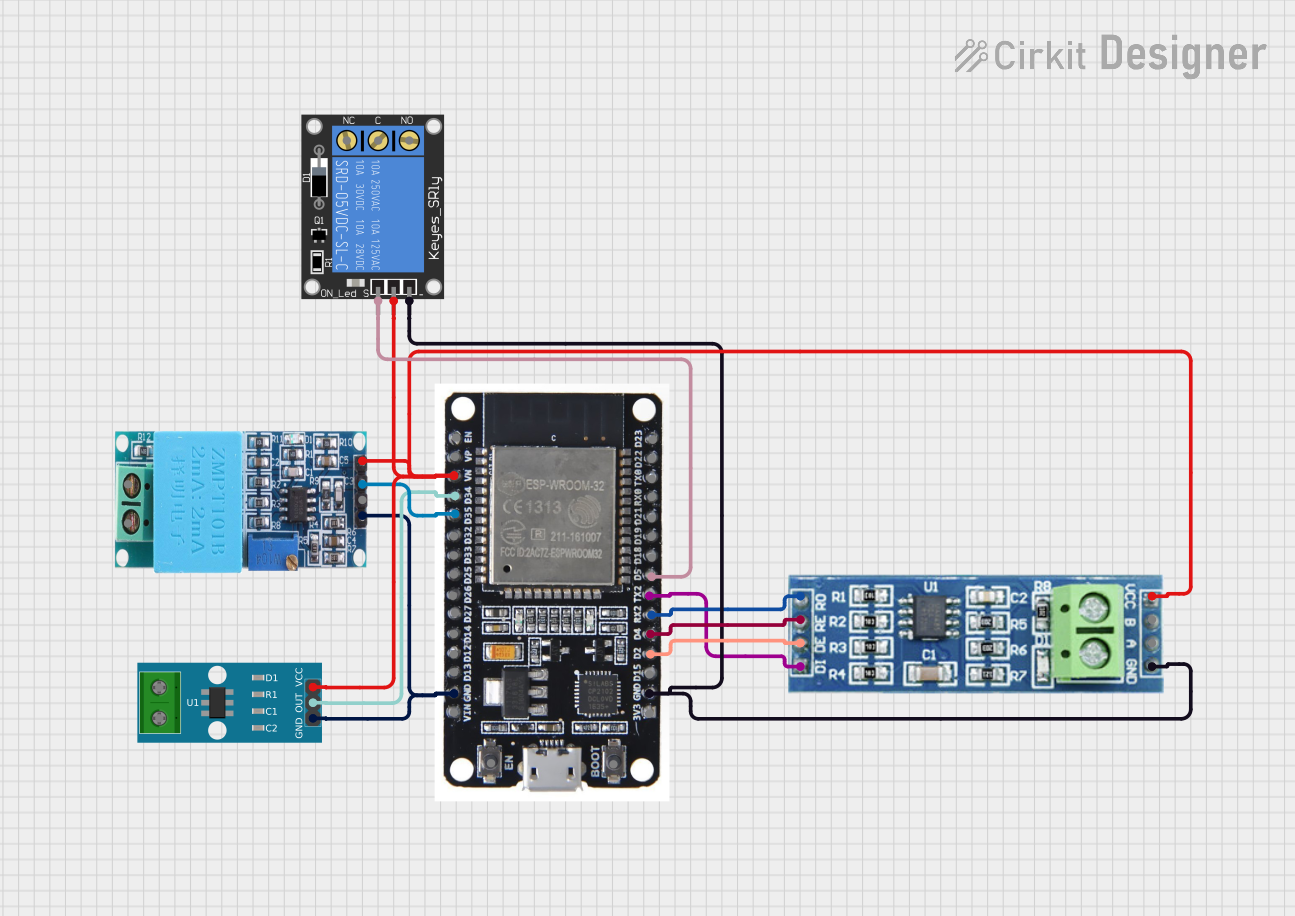
How to Use the Component in a Circuit

  1. Power the Module: Connect the VCC pin to a 5V DC power source and the GND pin to ground.
  2. Connect Communication Lines:
    • For RS485: Connect the A and B lines to the RS485 bus.
    • For RS232 TTL: Connect the TXD and RXD pins to the corresponding pins on your microcontroller or PC.
  3. Connect Load Devices:
    • For each relay, connect the load device to the COMx and NOx (or NCx) terminals, depending on whether you want the device to be normally off or on.
  4. Send Commands:
    • Use the Modbus RTU protocol or RS232 commands to control the relays. Each relay can be turned on or off independently.

Important Considerations and Best Practices

  • Ensure the total current drawn by the relays does not exceed the power supply's capacity.
  • Use proper shielding and grounding for RS485 communication lines to minimize noise.
  • Avoid switching high-inductive loads without proper snubber circuits to protect the relays.
  • Configure the baud rate and Modbus address correctly to avoid communication conflicts.

Example Code for Arduino UNO (RS232 TTL)

#include <SoftwareSerial.h>

// Define RX and TX pins for RS232 communication
SoftwareSerial RS232(10, 11); // RX = pin 10, TX = pin 11

void setup() {
  RS232.begin(9600); // Initialize RS232 communication at 9600 bps
  Serial.begin(9600); // Initialize serial monitor for debugging

  // Example: Turn on relay 1
  byte command[] = {0x01, 0x05, 0x00, 0x00, 0xFF, 0x00, 0x8C, 0x3A};
  RS232.write(command, sizeof(command));
  Serial.println("Relay 1 ON command sent");
}

void loop() {
  // Add your logic here to control relays dynamically
}

Note: The above code sends a Modbus RTU command to turn on relay 1. Modify the command bytes to control other relays or perform additional actions.

Troubleshooting and FAQs

Common Issues and Solutions

  1. Relays Not Responding:

    • Cause: Incorrect power supply or communication settings.
    • Solution: Verify the power supply voltage is 5V DC and check the baud rate and Modbus address.
  2. Communication Errors:

    • Cause: Noise on RS485 lines or incorrect wiring.
    • Solution: Use twisted-pair cables for RS485 and ensure proper termination resistors are in place.
  3. Relays Stuck in One State:

    • Cause: Faulty relay or excessive load current.
    • Solution: Check the load current and replace the relay if necessary.
  4. Overheating:

    • Cause: Continuous high-current operation.
    • Solution: Ensure adequate ventilation and avoid exceeding the relay's current rating.

FAQs

  • Q: Can I use this module with a 3.3V microcontroller?
    A: Yes, but you will need a level shifter for the RS232 TTL communication lines.

  • Q: How do I change the Modbus address?
    A: Refer to the module's datasheet for instructions on configuring the address via DIP switches or software commands.

  • Q: Can I control all 8 relays simultaneously?
    A: Yes, you can send commands to control multiple relays at once using the Modbus RTU protocol.

  • Q: Is the module compatible with Raspberry Pi?
    A: Yes, the module can be used with Raspberry Pi via RS485 or RS232 TTL communication.