How to Use 10BASET1S MAC-PHY evaluation board: Examples, Pinouts, and Specs
Introduction
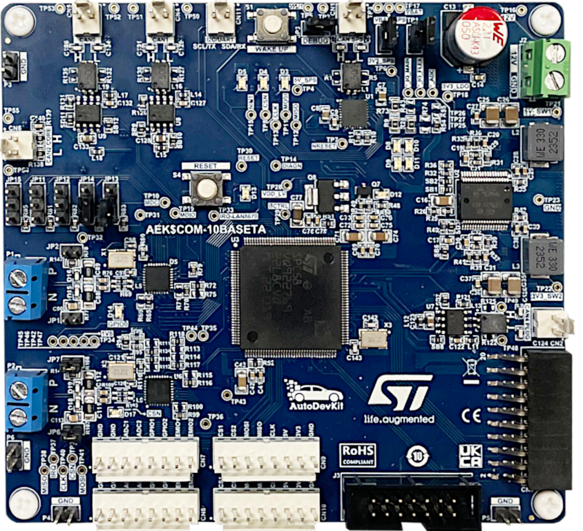
The AEK-COM-10BASET1S is a development board from STMicroelectronics designed for evaluating the performance and functionality of 10BASE-T1S MAC-PHY devices. This board is tailored for low-power Ethernet applications, making it ideal for industrial and automotive environments where robust and efficient communication is essential.
Explore Projects Built with 10BASET1S MAC-PHY evaluation board
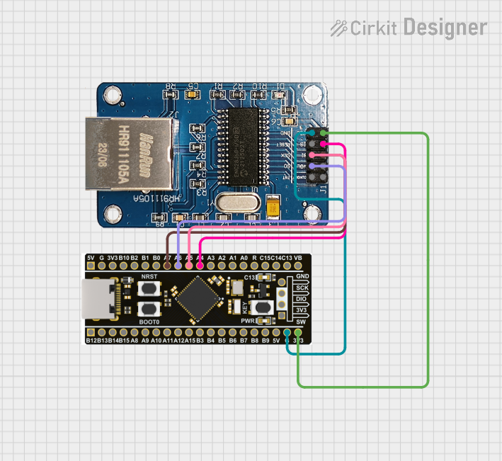
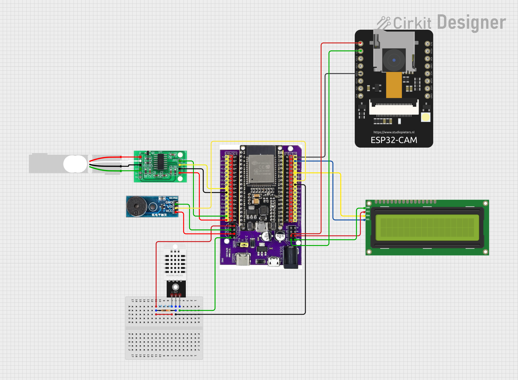


Explore Projects Built with 10BASET1S MAC-PHY evaluation board
Common Applications and Use Cases
- Industrial Automation: Enables reliable Ethernet communication in factory automation systems.
- Automotive Networking: Facilitates in-vehicle Ethernet communication for advanced driver-assistance systems (ADAS) and infotainment.
- IoT Devices: Provides a low-power Ethernet solution for IoT edge devices.
- Embedded Systems Development: Serves as a platform for prototyping and testing Ethernet-based embedded systems.
Technical Specifications
Key Technical Details
- Ethernet Standard: 10BASE-T1S (IEEE 802.3cg compliant)
- Power Supply: 3.3V or 5V DC input
- Communication Interface: SPI (Serial Peripheral Interface) for host communication
- Operating Temperature: -40°C to +85°C
- Connector Type: Single-pair Ethernet (SPE) interface
- MAC-PHY Device: Integrated 10BASE-T1S MAC-PHY transceiver
- Dimensions: Compact form factor for easy integration into test setups
Pin Configuration and Descriptions
The AEK-COM-10BASET1S evaluation board features a set of pins for power, communication, and control. Below is the pin configuration:
| Pin Name | Type | Description |
|---|---|---|
| VCC | Power Input | 3.3V or 5V DC power supply input. |
| GND | Power Ground | Ground connection for the board. |
| SPI_MOSI | Digital Input | SPI Master Out Slave In (data input to the MAC-PHY). |
| SPI_MISO | Digital Output | SPI Master In Slave Out (data output from the MAC-PHY). |
| SPI_SCK | Digital Input | SPI clock signal for synchronization. |
| SPI_CS | Digital Input | SPI chip select signal to enable communication with the MAC-PHY. |
| RESET | Digital Input | Active-low reset pin to initialize the MAC-PHY. |
| INT | Digital Output | Interrupt signal to notify the host of events or status changes. |
| TXP | Analog Output | Transmit data positive signal for the single-pair Ethernet interface. |
| TXN | Analog Output | Transmit data negative signal for the single-pair Ethernet interface. |
| RXP | Analog Input | Receive data positive signal from the single-pair Ethernet interface. |
| RXN | Analog Input | Receive data negative signal from the single-pair Ethernet interface. |
Usage Instructions
How to Use the Component in a Circuit
- Power Supply: Connect the VCC pin to a 3.3V or 5V DC power source and the GND pin to ground.
- SPI Communication: Connect the SPI pins (MOSI, MISO, SCK, and CS) to the corresponding SPI pins on your microcontroller or host device.
- Ethernet Interface: Connect the TXP/TXN and RXP/RXN pins to a single-pair Ethernet cable for communication.
- Reset and Interrupt: Use the RESET pin to initialize the MAC-PHY and monitor the INT pin for status updates or events.
- Host Configuration: Configure the host microcontroller to communicate with the MAC-PHY using the SPI protocol.
Important Considerations and Best Practices
- Ensure the power supply voltage matches the board's requirements (3.3V or 5V).
- Use shielded cables for the single-pair Ethernet interface to minimize noise and interference.
- Properly terminate the Ethernet cable to meet the 10BASE-T1S standard.
- Avoid hot-plugging the board to prevent damage to the components.
- Follow the SPI timing requirements specified in the MAC-PHY datasheet for reliable communication.
Example Code for Arduino UNO
Below is an example of how to interface the AEK-COM-10BASET1S with an Arduino UNO using SPI:
#include <SPI.h>

// Pin definitions
const int CS_PIN = 10;  // Chip Select pin
const int RESET_PIN = 9; // Reset pin
const int INT_PIN = 2;   // Interrupt pin

void setup() {
  // Initialize serial communication for debugging
  Serial.begin(9600);

  // Configure SPI pins
  pinMode(CS_PIN, OUTPUT);
  pinMode(RESET_PIN, OUTPUT);
  pinMode(INT_PIN, INPUT);

  // Initialize SPI
  SPI.begin();
  digitalWrite(CS_PIN, HIGH); // Set CS pin high (inactive)

  // Reset the MAC-PHY
  digitalWrite(RESET_PIN, LOW);
  delay(10); // Hold reset low for 10ms
  digitalWrite(RESET_PIN, HIGH);

  Serial.println("10BASE-T1S MAC-PHY initialized.");
}

void loop() {
  // Example: Send a command to the MAC-PHY
  digitalWrite(CS_PIN, LOW); // Select the MAC-PHY
  SPI.transfer(0x01); // Example command byte
  digitalWrite(CS_PIN, HIGH); // Deselect the MAC-PHY

  // Check for interrupt
  if (digitalRead(INT_PIN) == LOW) {
    Serial.println("Interrupt received from MAC-PHY.");
  }

  delay(1000); // Wait for 1 second
}
Troubleshooting and FAQs
Common Issues and Solutions
No Communication with the MAC-PHY
- Cause: Incorrect SPI configuration or wiring.
- Solution: Verify the SPI connections and ensure the SPI clock speed matches the MAC-PHY's requirements.
Interrupt Pin Not Responding
- Cause: The MAC-PHY is not properly initialized.
- Solution: Check the RESET pin connection and ensure the initialization sequence is followed.
Ethernet Communication Fails
- Cause: Improper cable termination or excessive noise.
- Solution: Use shielded cables and ensure proper termination as per the 10BASE-T1S standard.
Board Overheating
- Cause: Incorrect power supply voltage.
- Solution: Ensure the power supply voltage is within the specified range (3.3V or 5V).
FAQs
Q: Can this board be used with 5V logic microcontrollers?
A: Yes, the board supports both 3.3V and 5V logic levels.Q: What is the maximum cable length supported by 10BASE-T1S?
A: The 10BASE-T1S standard supports cable lengths of up to 25 meters.Q: Is the board compatible with other microcontrollers besides Arduino?
A: Yes, the board can be used with any microcontroller that supports SPI communication.Q: Can I use this board for multi-drop Ethernet networks?
A: Yes, the 10BASE-T1S standard supports multi-drop networks with up to 8 nodes.
This documentation provides a comprehensive guide to using the AEK-COM-10BASET1S evaluation board for 10BASE-T1S MAC-PHY applications. For further details, refer to the official datasheet and user manual from STMicroelectronics.