How to Use 7-Segment Display (4 Digit): Examples, Pinouts, and Specs
Introduction
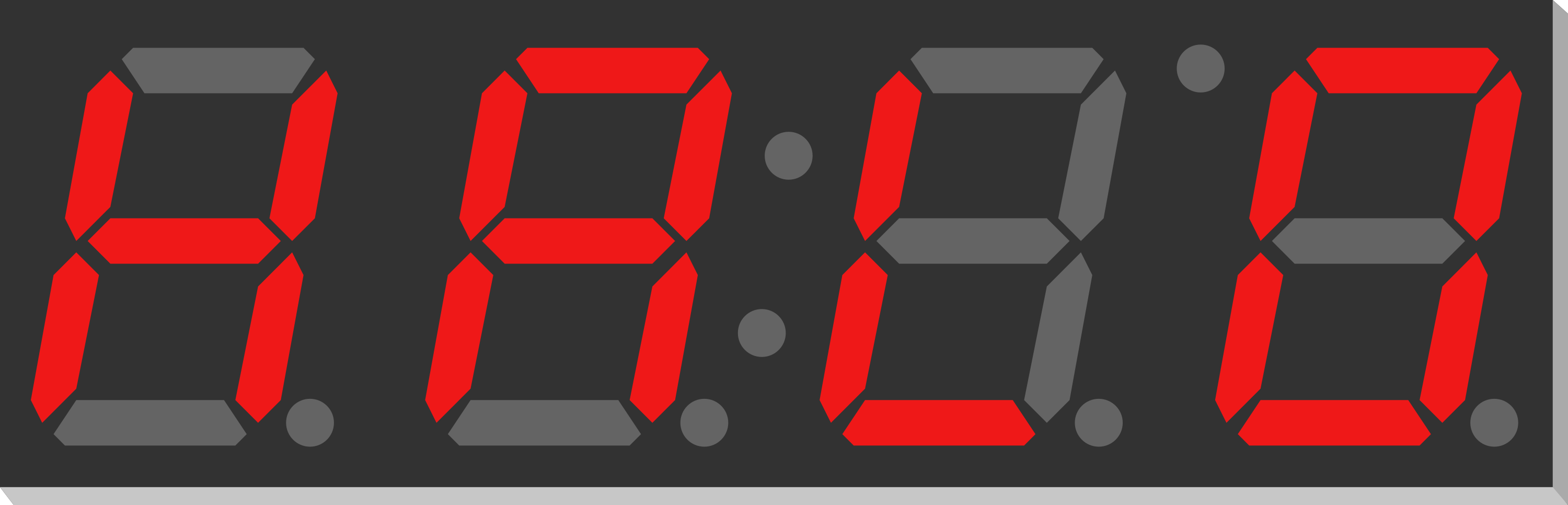
A 7-Segment Display is an electronic display device used to show decimal numerals and, in some cases, a limited number of alphabetical characters. It is commonly found in digital clocks, electronic meters, and other devices that display numerical information. The 4-digit 7-segment display consists of four individual digit displays, each composed of seven segments that can be turned on or off to create a visual representation of an alphanumeric character. These displays are widely used in projects that require a simple, cost-effective user interface.
Explore Projects Built with 7-Segment Display (4 Digit)
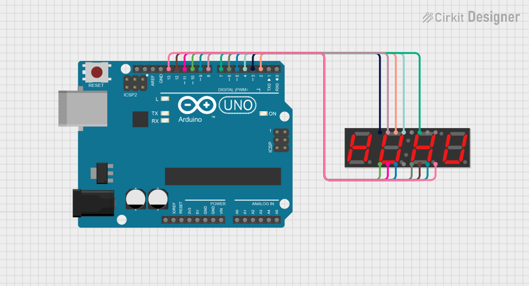
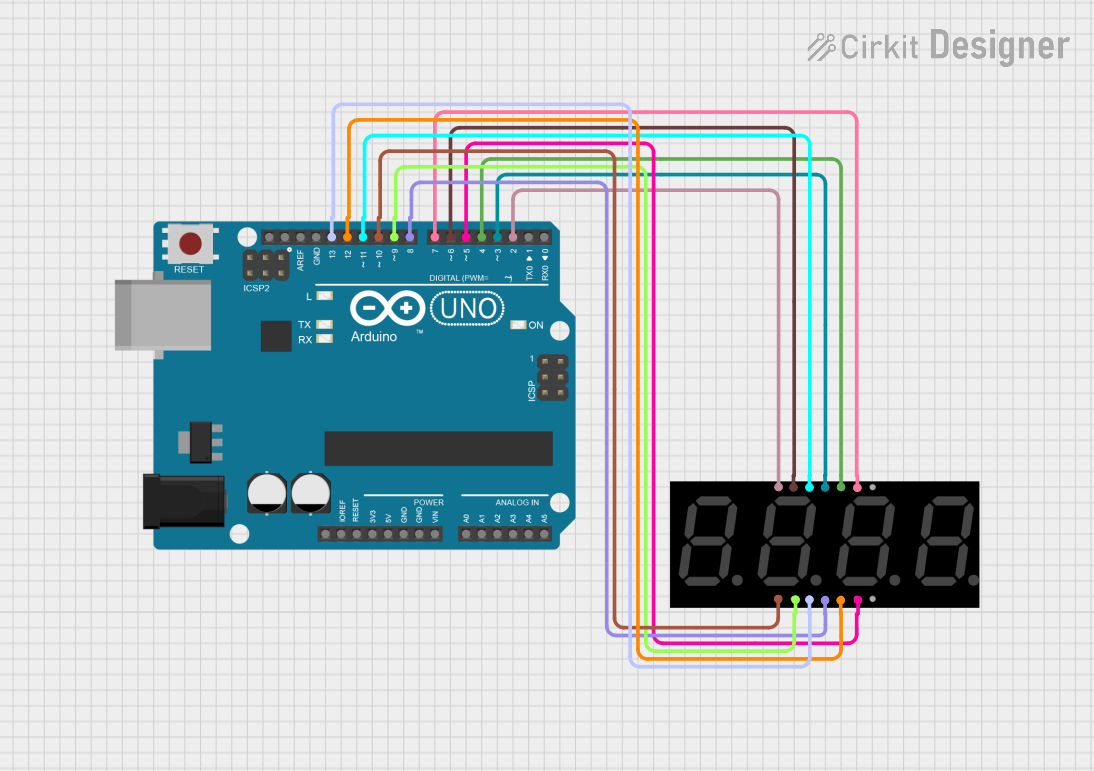
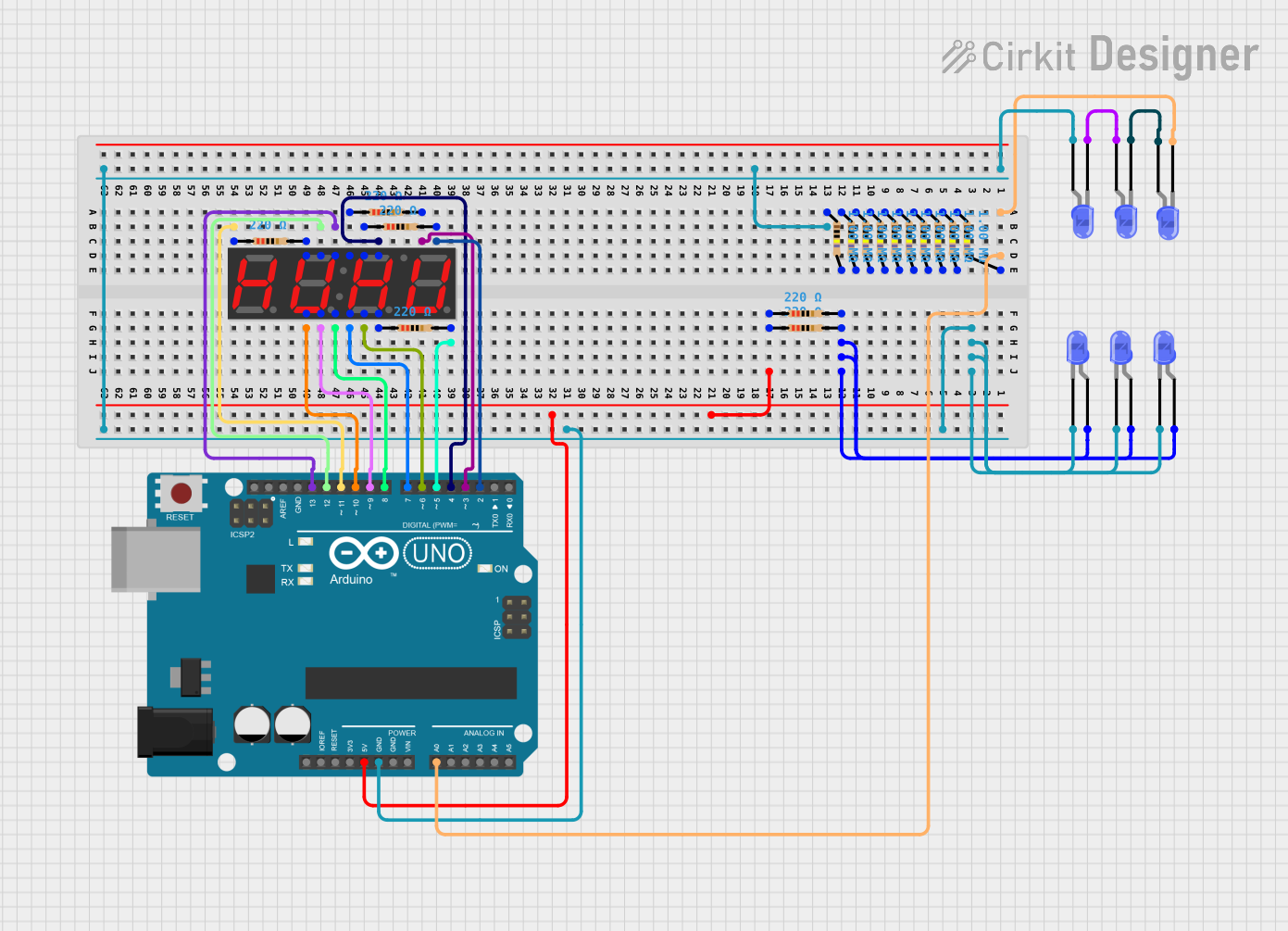
Explore Projects Built with 7-Segment Display (4 Digit)
Common Applications and Use Cases
- Digital clocks and timers
- Counters and scoreboards
- Calculators
- Electronic meters (like voltmeters, ammeters)
- Price display boards
Technical Specifications
Key Technical Details
- Operating Voltage: Typically 3.3V to 5V
- Forward Current (per segment): 10-20 mA
- Peak Forward Current (per segment): 100 mA (Pulse operation)
- Reverse Voltage (per segment): 5V maximum
- Power Dissipation (per segment): 100 mW
Pin Configuration and Descriptions
| Pin Number | Function | Description |
|---|---|---|
| 1 | Digit 1 Anode | Controls the first digit (leftmost) |
| 2 | Digit 2 Anode | Controls the second digit |
| 3 | Digit 3 Anode | Controls the third digit |
| 4 | Digit 4 Anode | Controls the fourth digit (rightmost) |
| 5-11 | Segment Cathode | Controls individual segments (A-G) |
| 12 | Decimal Point | Controls the decimal point (DP) |
Note: The actual pin configuration may vary based on the manufacturer. Always refer to the manufacturer's datasheet for exact details.
Usage Instructions
How to Use the Component in a Circuit
- Connect the common anode pins of the display to the positive supply voltage (Vcc).
- Connect the cathode pins of the segments you wish to illuminate through current-limiting resistors to ground.
- To display a number, activate the corresponding segments for each digit by grounding their cathode pins.
- To prevent ghosting when multiplexing, ensure only one digit is active at any given time.
Important Considerations and Best Practices
- Always use current-limiting resistors with each segment to prevent damage to the LEDs.
- When multiplexing, ensure that the refresh rate is high enough to avoid flickering.
- Be mindful of the power dissipation when all segments are lit, as this can cause excessive heat.
Example Code for Arduino UNO
#include <SevSeg.h>
SevSeg sevseg; //Instantiate a seven segment controller object

void setup() {
  byte numDigits = 4;
  byte digitPins[] = {2, 3, 4, 5};
  byte segmentPins[] = {6, 7, 8, 9, 10, 11, 12, 13};
  bool resistorsOnSegments = false; // 'false' means resistors are on digit pins
  byte hardwareConfig = COMMON_ANODE; // See README.md for options
  bool updateWithDelays = false; // Default 'false' is Recommended
  bool leadingZeros = false; // Use 'true' if you'd like to keep the leading zeros
  bool disableDecPoint = true; // Use 'true' if your display has no decimal point

  sevseg.begin(hardwareConfig, numDigits, digitPins, segmentPins, resistorsOnSegments,
               updateWithDelays, leadingZeros, disableDecPoint);
  sevseg.setBrightness(90); // Set brightness level (0 is min, 100 is max)
}

void loop() {
  sevseg.setNumber(1234, 0); // Set the number to be displayed and decimal places
  sevseg.refreshDisplay(); // Must run repeatedly within loop()
}
Note: The above code uses the SevSeg library to control a 4-digit 7-segment display. Make sure to install the SevSeg library through the Arduino Library Manager before compiling.
Troubleshooting and FAQs
Common Issues Users Might Face
- Segments not lighting up: Check the connections and ensure that the current-limiting resistors are correctly placed.
- Dim display: Ensure that the power supply voltage is adequate and that the brightness setting is correctly adjusted.
- Ghosting between digits: This can occur if multiple digits are active simultaneously during multiplexing. Ensure proper timing in the code.
Solutions and Tips for Troubleshooting
- Double-check wiring against the datasheet and ensure all connections are secure.
- Verify that the current-limiting resistors are of the correct value.
- Use a multimeter to check for continuity and proper voltage levels at each segment.
- Review the code for proper multiplexing and refresh rate.
FAQs
Q: Can I use a 4-digit 7-segment display with a microcontroller that operates at 3.3V? A: Yes, but ensure that the display is compatible with 3.3V logic, and adjust the current-limiting resistors accordingly.
Q: How do I control each segment individually? A: Each segment is controlled by its corresponding cathode pin. Grounding a segment's pin will light it up, assuming the common anode is connected to Vcc.
Q: What is multiplexing, and why is it used? A: Multiplexing is a technique used to control multiple digits with fewer I/O pins by rapidly switching them on and off in sequence. This creates the illusion that all digits are lit simultaneously.
Q: Can I display letters on a 7-segment display? A: Yes, some letters can be displayed, but they are limited due to the segment structure. For example, "A," "b," "C," "d," "E," "F," "H," "L," "P," and a few others can be represented.
Remember to always refer to the specific datasheet of the 7-segment display model you are using for precise information and recommendations.