How to Use Rotary Encoder: Examples, Pinouts, and Specs
Introduction
A rotary encoder is an electro-mechanical device that converts the angular position or motion of a shaft into analog or digital output signals. Rotary encoders are widely used in various applications, including industrial controls, robotics, position sensing, and user input devices like volume controls and navigational menus.
Explore Projects Built with Rotary Encoder
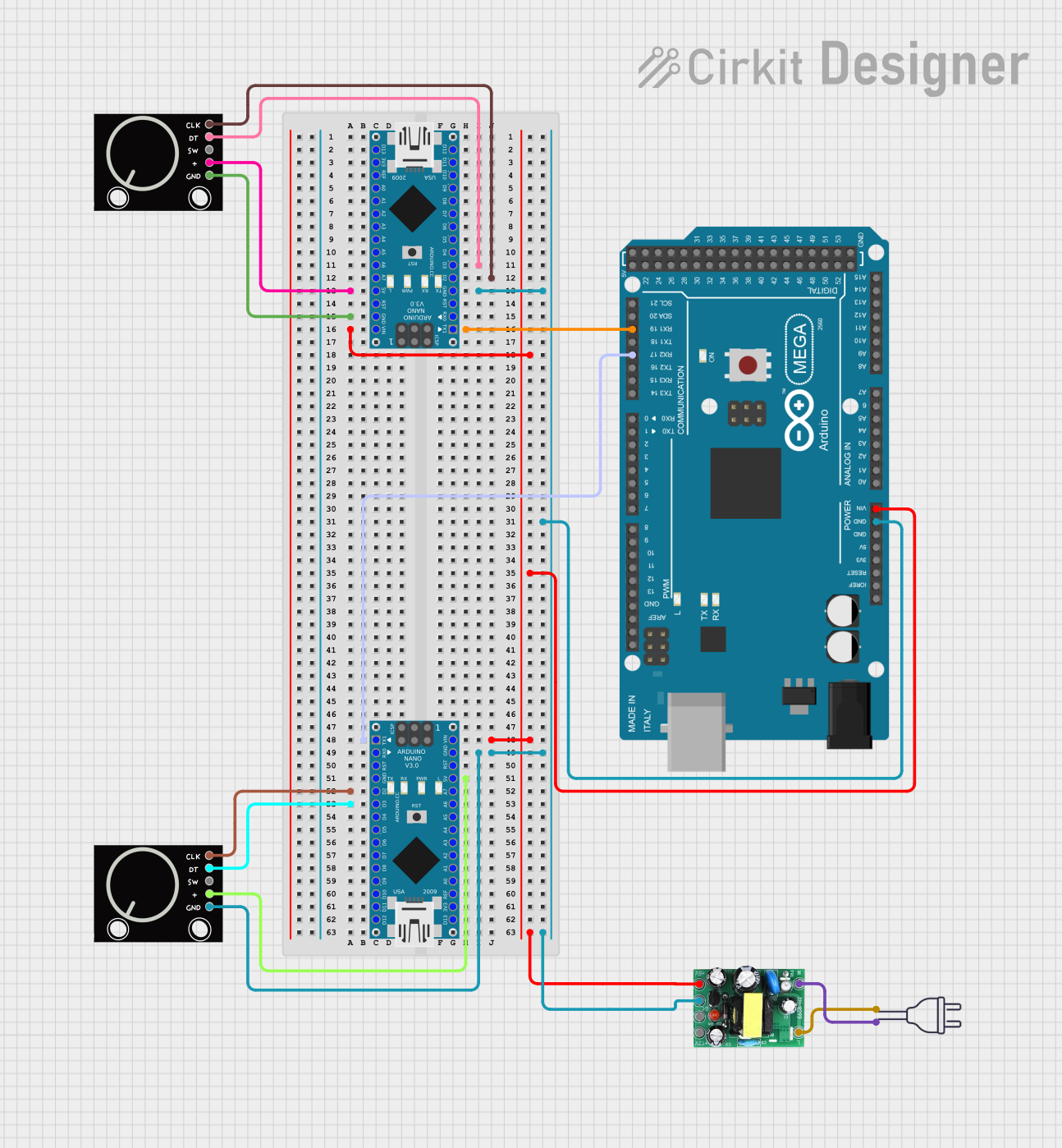
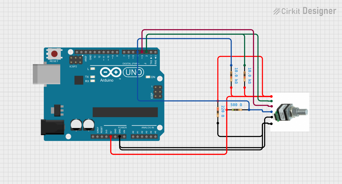
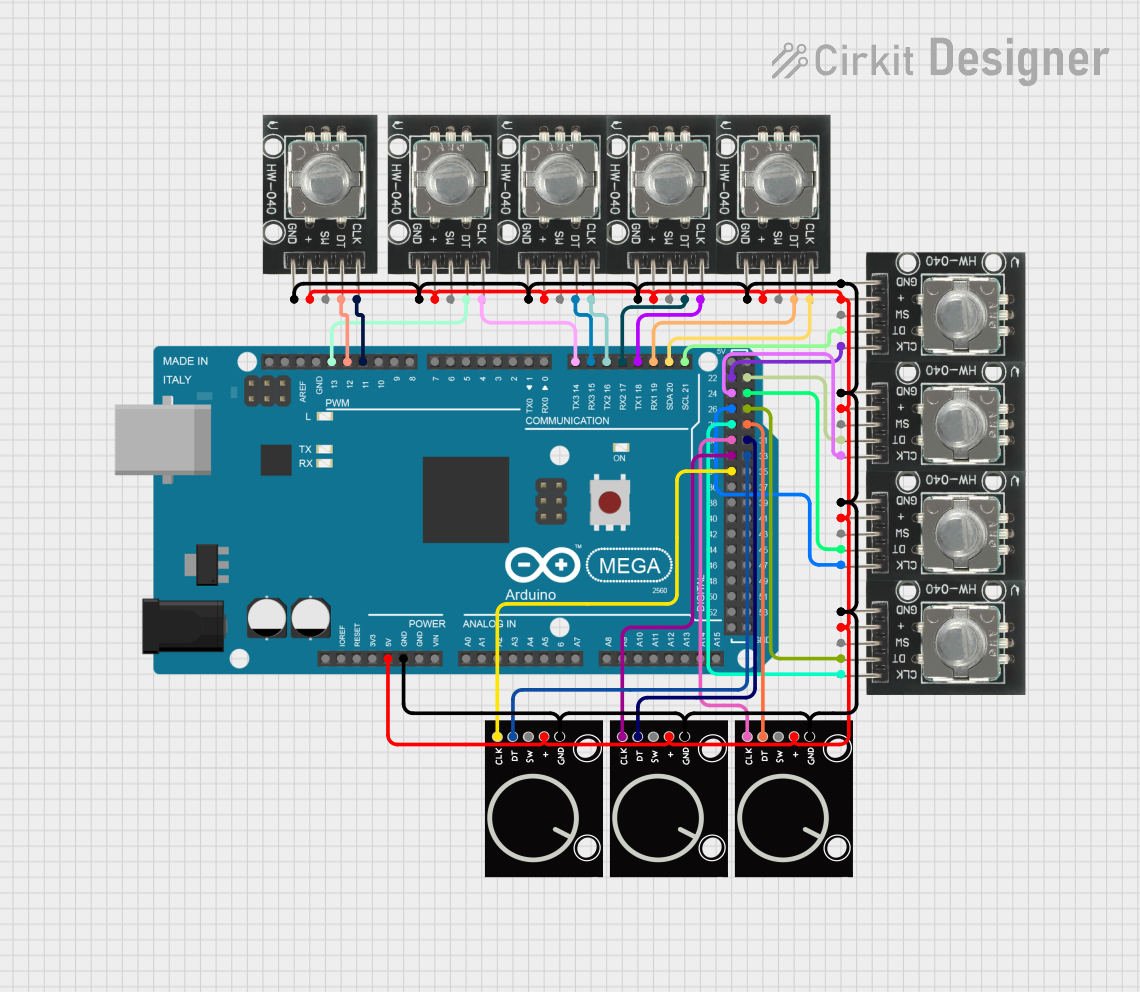
Explore Projects Built with Rotary Encoder
Common Applications and Use Cases
- Position Sensing: Rotary encoders are used to determine the position of a moving part.
- Speed Control: They can monitor and report the speed of a rotating shaft.
- User Input: Encoders provide input for devices, allowing users to scroll through menus or adjust settings.
- Industrial Automation: They are integral in control systems for feedback on motor positioning.
Technical Specifications
Key Technical Details
- Voltage Rating: 3.3V to 5V
- Current Rating: 10mA to 30mA
- Output Signal: Quadrature (Incremental) or Absolute
- Resolution: Typically ranges from 12 to 1024 pulses per revolution (PPR)
Pin Configuration and Descriptions
| Pin Number | Name | Description |
|---|---|---|
| 1 | VCC | Power supply (3.3V to 5V) |
| 2 | GND | Ground connection |
| 3 | OUTA | Output A - Quadrature output 1 |
| 4 | OUTB | Output B - Quadrature output 2 |
| 5 | SW | Switch (push button) |
Usage Instructions
How to Use the Component in a Circuit
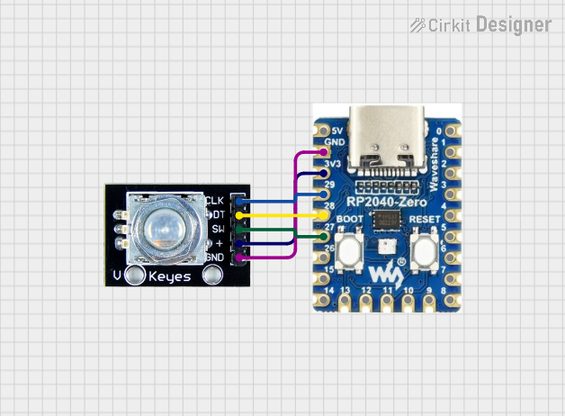
- Power Connection: Connect the VCC pin to a 3.3V or 5V power supply and the GND pin to the ground.
- Output Connection: Connect OUTA and OUTB to two digital input pins on a microcontroller to read the encoder's rotation.
- Button Connection: If the encoder has a push-button switch, connect the SW pin to another digital input pin.
Important Considerations and Best Practices
- Debouncing: Rotary encoders are mechanical devices and may require debouncing, either through hardware or software, to ensure accurate readings.
- Pull-Up Resistors: Use pull-up resistors on the output lines to ensure a stable high signal when the contacts are open.
- Interrupts: For more accurate reading, use interrupts on the microcontroller to detect changes in the encoder's output.
Example Code for Arduino UNO
// Define the pins for the rotary encoder
const int encoderPinA = 2; // Output A
const int encoderPinB = 3; // Output B
const int buttonPin = 4;   // Push button switch

volatile int lastEncoded = 0;
volatile long encoderValue = 0;

void setup() {
  pinMode(encoderPinA, INPUT_PULLUP);
  pinMode(encoderPinB, INPUT_PULLUP);
  pinMode(buttonPin, INPUT_PULLUP);

  // Set up interrupts for the encoder pins
  attachInterrupt(digitalPinToInterrupt(encoderPinA), updateEncoder, CHANGE);
  attachInterrupt(digitalPinToInterrupt(encoderPinB), updateEncoder, CHANGE);
}

void loop() {
  // Use encoderValue for your application
}

void updateEncoder() {
  int MSB = digitalRead(encoderPinA); // Most significant bit
  int LSB = digitalRead(encoderPinB); // Least significant bit

  int encoded = (MSB << 1) | LSB; // Converting the 2 pin value to single number
  int sum = (lastEncoded << 2) | encoded; // Adding it to the previous encoded value

  if(sum == 0b1101 || sum == 0b0100 || sum == 0b0010 || sum == 0b1011) encoderValue++;
  if(sum == 0b1110 || sum == 0b0111 || sum == 0b0001 || sum == 0b1000) encoderValue--;

  lastEncoded = encoded; // Store this value for next time
}
Troubleshooting and FAQs
Common Issues Users Might Face
- Inaccurate Readings: This can be due to noise or debouncing issues. Implement software debouncing or add hardware debouncing circuits.
- No Response: Ensure that the encoder is powered correctly and that the pins are connected to the correct microcontroller pins.
- Erratic Behavior: Check for loose connections or damaged components. Also, ensure that pull-up resistors are in place if required.
Solutions and Tips for Troubleshooting
- Debouncing: Implement a simple software debounce using delay functions or more advanced techniques like state machines.
- Check Connections: Verify all connections are secure and correct. Use a multimeter to ensure continuity where expected.
- Pull-Up Resistors: If not using internal pull-ups, add external pull-up resistors (typically 10kΩ) to the output lines.
FAQs
Q: Can I use a rotary encoder with an Arduino without external libraries?
A: Yes, you can use interrupts as shown in the example code, or you can poll the encoder in the loop() function.
Q: How do I know if my rotary encoder is incremental or absolute? A: Incremental encoders provide relative position with no fixed start or end point, while absolute encoders provide a unique position for each angle of the shaft. Check the datasheet of your specific encoder to determine its type.
Q: What is the purpose of the push-button on some rotary encoders? A: The push-button can be used as a user input, often to select an option after scrolling through a menu with the encoder.