How to Use Sharp IR Sensor: Examples, Pinouts, and Specs
Introduction
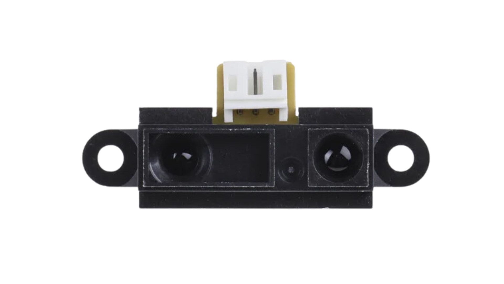
The Sharp IR Sensor is an infrared distance-measuring component widely used in robotics, automation, and interactive projects. It operates by emitting an infrared signal and then detecting the angle of the reflected signal to determine the distance to an object. This sensor is favored for its ease of use, non-contact measurement capability, and relatively long detection range.
Explore Projects Built with Sharp IR Sensor
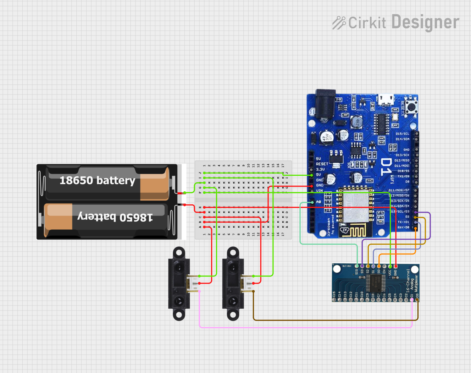
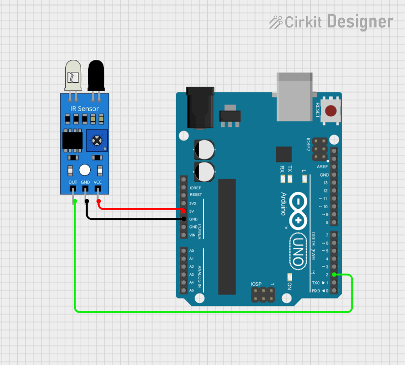

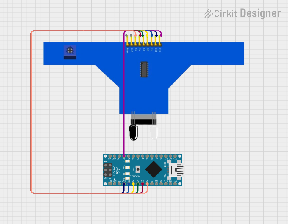
Explore Projects Built with Sharp IR Sensor
Common Applications and Use Cases
- Obstacle avoidance for robots
- Proximity detection in interactive installations
- Line following robots and edge detection
- Position and level measurement
Technical Specifications
Key Technical Details
- Operating Voltage: Typically 4.5V to 5.5V
- Average Current Consumption: 30 to 50 mA
- Measuring Range: Varies by model (e.g., 10 to 80 cm for GP2Y0A21YK)
- Output Type: Analog voltage corresponding to distance
- Response Time: 38 ± 10 ms
Pin Configuration and Descriptions
| Pin Number | Name | Description |
|---|---|---|
| 1 | Vcc | Power supply (4.5V to 5.5V) |
| 2 | GND | Ground connection |
| 3 | Vo | Output voltage (analog) |
Usage Instructions
How to Use the Component in a Circuit
- Connect the Vcc pin to the 5V output on your microcontroller or power supply.
- Connect the GND pin to the ground of your system.
- Connect the Vo pin to an analog input on your microcontroller to read the distance value.
Important Considerations and Best Practices
- Ensure that the power supply is stable and within the specified voltage range.
- Avoid exposing the sensor to direct sunlight or strong infrared sources, as this can interfere with measurements.
- Keep the sensor's lens clean and unobstructed.
- Calibrate the sensor for your specific application, as the output can vary between units.
Example Code for Arduino UNO
// Sharp IR Sensor to Arduino UNO Example

const int irPin = A0; // Analog input pin connected to the sensor's output

void setup() {
  Serial.begin(9600); // Start serial communication at 9600 baud
}

void loop() {
  int sensorValue = analogRead(irPin); // Read the sensor output
  float voltage = sensorValue * (5.0 / 1023.0); // Convert to voltage
  // Convert the voltage to distance (example for GP2Y0A21YK sensor)
  float distance = 27.86 * pow(voltage, -1.15); // Distance in cm (approximation)

  Serial.print("Distance: ");
  Serial.print(distance); // Print the distance
  Serial.println(" cm");

  delay(100); // Wait for 100 milliseconds before next reading
}
Troubleshooting and FAQs
Common Issues Users Might Face
- Inaccurate Readings: Ensure there are no obstructions or reflective surfaces near the sensor that could cause false readings.
- No Output: Check the wiring and ensure the sensor is receiving the correct voltage.
- Fluctuating Readings: Stabilize the power supply and avoid electrical noise.
Solutions and Tips for Troubleshooting
- If the readings are inconsistent, try averaging multiple readings to get a more stable value.
- Calibrate the sensor using known distances to improve accuracy.
- Use capacitors to filter out noise from the power supply if necessary.
FAQs
Q: Can the sensor measure through transparent objects? A: No, the sensor cannot reliably measure distance through transparent materials as the infrared light may pass through or reflect unpredictably.
Q: What is the sensor's field of view? A: The field of view varies by model but is typically around 20 to 40 degrees. Objects within this angle range can be detected.
Q: How do I calibrate the sensor for precise measurements? A: Measure known distances and record the sensor's output voltage. Create a calibration curve or function to translate voltage to distance accurately for your application.