Cirkit Designer Logo
Cirkit Designer
Your all-in-one circuit design IDE
Home / 
Component Documentation

How to Use Gearmotor: Examples, Pinouts, and Specs

Image of Gearmotor
Cirkit Designer LogoDesign with Gearmotor in Cirkit Designer

Introduction

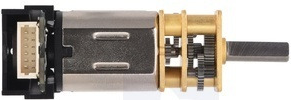
A gearmotor is an electric motor integrated with a gear reducer, designed to deliver high torque at low speeds. The gear reducer modifies the motor's output by reducing its speed while increasing torque, making it ideal for applications requiring precise motion control. Gearmotors are widely used in robotics, conveyor systems, automated machinery, and other applications where controlled movement and high torque are essential.

Explore Projects Built with Gearmotor

Use Cirkit Designer to design, explore, and prototype these projects online. Some projects support real-time simulation. Click "Open Project" to start designing instantly!
ESP32 and L298N Motor Driver Controlled Battery-Powered Robotic Car
Image of ESP 32 BT BOT: A project utilizing Gearmotor in a practical application
This circuit is a motor control system powered by a 12V battery, utilizing an L298N motor driver to control four DC gearmotors. An ESP32 microcontroller is used to send control signals to the motor driver, enabling precise control of the motors for applications such as a robotic vehicle.
Cirkit Designer LogoOpen Project in Cirkit Designer
Arduino-Controlled Bluetooth Robotic Vehicle with Ultrasonic Navigation
Image of BOAT 2: A project utilizing Gearmotor in a practical application
This circuit is designed to remotely control two DC gearmotors using an Arduino UNO and an L298N motor driver, with an HC-05 Bluetooth module for wireless communication. It includes a JSN-SR04T ultrasonic sensor for distance measurement and a TM1637 display for output. Power management is handled by an 18650 Li-Ion battery and rocker switches.
Cirkit Designer LogoOpen Project in Cirkit Designer
Arduino-Controlled Robotic Vehicle with IR Obstacle Detection and L298N Motor Driver
Image of LFR Car Circuit: A project utilizing Gearmotor in a practical application
This circuit controls two DC gearmotors using an L298N motor driver, which is interfaced with an Arduino Leonardo microcontroller. The Arduino adjusts the speed and direction of the motors through PWM and digital control signals. Power is supplied by a 3xAA battery pack, regulated to the appropriate voltage by an LM2596 step-down module, and an array of IR sensors are connected to the Arduino's analog inputs for potential object detection or line following functionalities.
Cirkit Designer LogoOpen Project in Cirkit Designer
Arduino-Controlled DC Motor with Encoder Feedback and Adjustable Speed
Image of gear motor: A project utilizing Gearmotor in a practical application
This circuit controls a gear motor with an integrated encoder using an L298N DC motor driver, which is interfaced with an Arduino Mega 2560 microcontroller. The motor's power is supplied by a 12V power source, which is also connected to an XL4015 DC Buck Step-down converter to provide a regulated 5V supply to the Arduino. The encoder outputs are connected to the Arduino for position or speed feedback, and the Arduino is programmed to manage the motor's speed and direction.
Cirkit Designer LogoOpen Project in Cirkit Designer

Explore Projects Built with Gearmotor

Use Cirkit Designer to design, explore, and prototype these projects online. Some projects support real-time simulation. Click "Open Project" to start designing instantly!
Image of ESP 32 BT BOT: A project utilizing Gearmotor in a practical application
ESP32 and L298N Motor Driver Controlled Battery-Powered Robotic Car
This circuit is a motor control system powered by a 12V battery, utilizing an L298N motor driver to control four DC gearmotors. An ESP32 microcontroller is used to send control signals to the motor driver, enabling precise control of the motors for applications such as a robotic vehicle.
Cirkit Designer LogoOpen Project in Cirkit Designer
Image of BOAT 2: A project utilizing Gearmotor in a practical application
Arduino-Controlled Bluetooth Robotic Vehicle with Ultrasonic Navigation
This circuit is designed to remotely control two DC gearmotors using an Arduino UNO and an L298N motor driver, with an HC-05 Bluetooth module for wireless communication. It includes a JSN-SR04T ultrasonic sensor for distance measurement and a TM1637 display for output. Power management is handled by an 18650 Li-Ion battery and rocker switches.
Cirkit Designer LogoOpen Project in Cirkit Designer
Image of LFR Car Circuit: A project utilizing Gearmotor in a practical application
Arduino-Controlled Robotic Vehicle with IR Obstacle Detection and L298N Motor Driver
This circuit controls two DC gearmotors using an L298N motor driver, which is interfaced with an Arduino Leonardo microcontroller. The Arduino adjusts the speed and direction of the motors through PWM and digital control signals. Power is supplied by a 3xAA battery pack, regulated to the appropriate voltage by an LM2596 step-down module, and an array of IR sensors are connected to the Arduino's analog inputs for potential object detection or line following functionalities.
Cirkit Designer LogoOpen Project in Cirkit Designer
Image of gear motor: A project utilizing Gearmotor in a practical application
Arduino-Controlled DC Motor with Encoder Feedback and Adjustable Speed
This circuit controls a gear motor with an integrated encoder using an L298N DC motor driver, which is interfaced with an Arduino Mega 2560 microcontroller. The motor's power is supplied by a 12V power source, which is also connected to an XL4015 DC Buck Step-down converter to provide a regulated 5V supply to the Arduino. The encoder outputs are connected to the Arduino for position or speed feedback, and the Arduino is programmed to manage the motor's speed and direction.
Cirkit Designer LogoOpen Project in Cirkit Designer

Technical Specifications

Below are the general technical specifications for a typical gearmotor. Note that specific values may vary depending on the model and manufacturer.

General Specifications

  • Input Voltage: 6V to 24V DC (varies by model)
  • Output Torque: 1 Nm to 50 Nm (depending on gear ratio)
  • Speed Range: 10 RPM to 500 RPM (varies by gear ratio)
  • Gear Ratio: 10:1 to 100:1 (common ranges)
  • Motor Type: Brushed DC or Brushless DC
  • Shaft Diameter: 4mm to 12mm (varies by model)
  • Operating Temperature: -10°C to 60°C

Pin Configuration and Descriptions

For a typical DC gearmotor with two terminals:

Pin/Terminal Description
Terminal 1 Positive terminal for motor input voltage (V+)
Terminal 2 Negative terminal for motor input voltage (V-)

For gearmotors with an encoder (optional feature):

Pin/Terminal Description
VCC Power supply for the encoder (e.g., 5V)
GND Ground connection for the encoder
A Encoder output signal A
B Encoder output signal B

Usage Instructions

How to Use the Gearmotor in a Circuit

  1. Power Supply: Connect the gearmotor to a DC power supply or motor driver. Ensure the voltage and current ratings match the gearmotor's specifications.
  2. Polarity: Reversing the polarity of the terminals will reverse the motor's rotation direction.
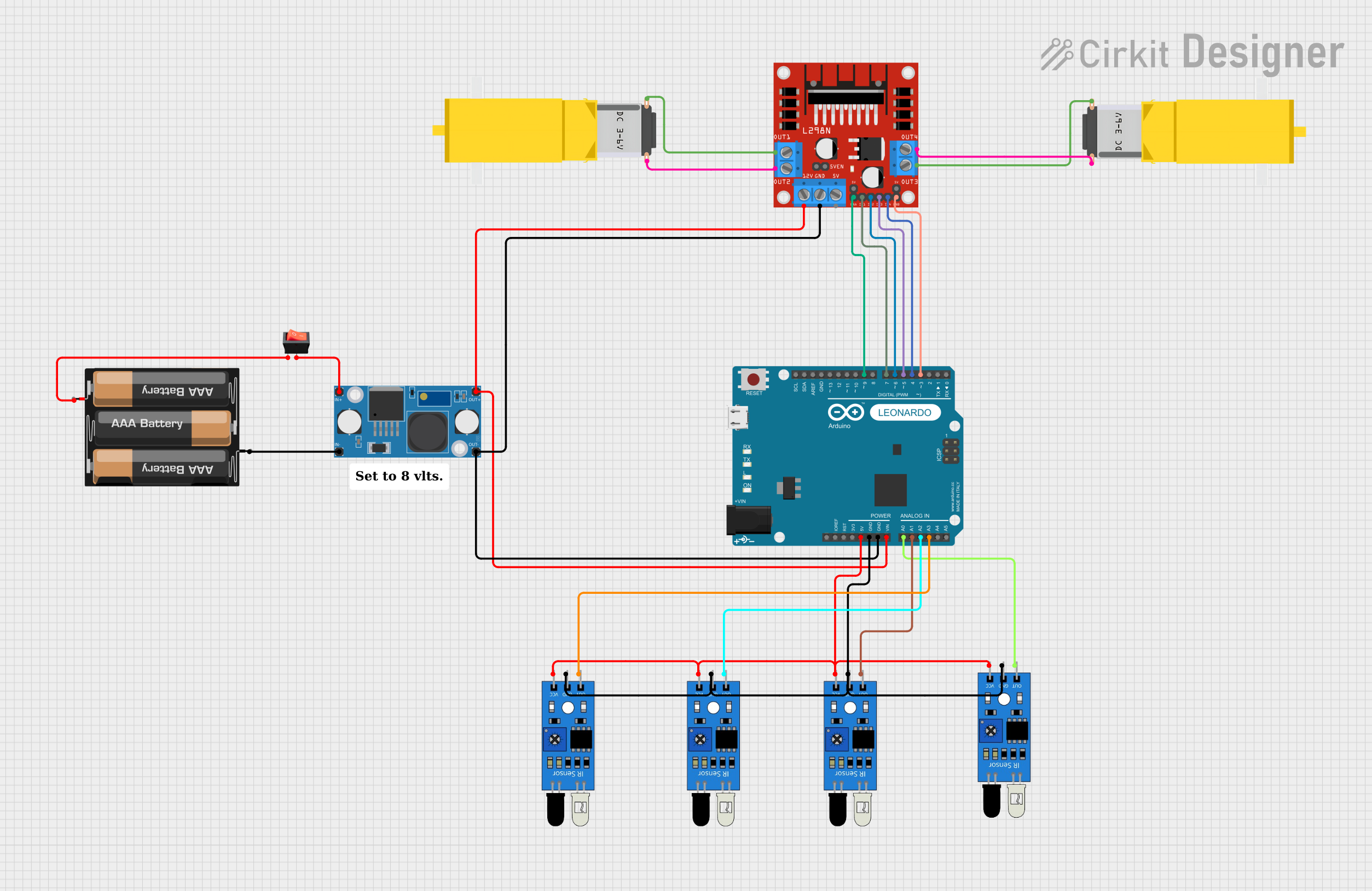
  3. Motor Driver: Use an H-bridge motor driver (e.g., L298N or L293D) to control the motor's speed and direction via PWM signals.
  4. Encoder (if available): Connect the encoder pins to a microcontroller (e.g., Arduino) to monitor the motor's position or speed.

Important Considerations and Best Practices

  • Avoid Overloading: Do not exceed the gearmotor's rated torque to prevent damage to the gears or motor.
  • Heat Dissipation: Ensure proper ventilation or heat sinking if the motor operates continuously under high load.
  • Power Supply: Use a stable and adequately rated power supply to avoid voltage drops or motor stalling.
  • Mounting: Securely mount the gearmotor to prevent misalignment or vibration during operation.

Example: Controlling a Gearmotor with Arduino UNO

Below is an example of controlling a gearmotor using an L298N motor driver and Arduino UNO.

// Include necessary pins for motor control
const int ENA = 9;  // PWM pin for speed control
const int IN1 = 8;  // Direction control pin 1
const int IN2 = 7;  // Direction control pin 2

void setup() {
  // Set motor control pins as outputs
  pinMode(ENA, OUTPUT);
  pinMode(IN1, OUTPUT);
  pinMode(IN2, OUTPUT);
}

void loop() {
  // Rotate motor in forward direction
  digitalWrite(IN1, HIGH);  // Set IN1 high
  digitalWrite(IN2, LOW);   // Set IN2 low
  analogWrite(ENA, 150);    // Set speed (0-255)

  delay(3000);  // Run motor for 3 seconds

  // Rotate motor in reverse direction
  digitalWrite(IN1, LOW);   // Set IN1 low
  digitalWrite(IN2, HIGH);  // Set IN2 high
  analogWrite(ENA, 150);    // Set speed (0-255)

  delay(3000);  // Run motor for 3 seconds
}

Troubleshooting and FAQs

Common Issues

  1. Motor Not Spinning:

    • Check the power supply voltage and current ratings.
    • Verify the connections to the motor driver or power source.
    • Ensure the motor driver is receiving the correct control signals.
  2. Motor Overheating:

    • Reduce the load on the motor.
    • Check for obstructions or excessive friction in the mechanical system.
    • Ensure proper ventilation or cooling.
  3. Inconsistent Speed or Torque:

    • Verify the power supply stability.
    • Check for loose connections or damaged wires.
    • If using an encoder, ensure proper signal connections to the microcontroller.

FAQs

Q: Can I use a gearmotor with an AC power source?
A: No, most gearmotors are designed for DC power. Use a DC power supply or motor driver compatible with the gearmotor's specifications.

Q: How do I select the right gearmotor for my application?
A: Consider the required torque, speed, voltage, and physical size. Choose a gear ratio that meets your application's torque and speed requirements.

Q: Can I control the speed of a gearmotor?
A: Yes, you can control the speed using a PWM signal via a motor driver or controller.

Q: What is the purpose of the encoder in a gearmotor?
A: The encoder provides feedback on the motor's position or speed, enabling precise control in applications like robotics or automation.

By following this documentation, you can effectively integrate and operate a gearmotor in your projects.