How to Use MCP3008 8-channel 10-bit ADC: Examples, Pinouts, and Specs
Introduction
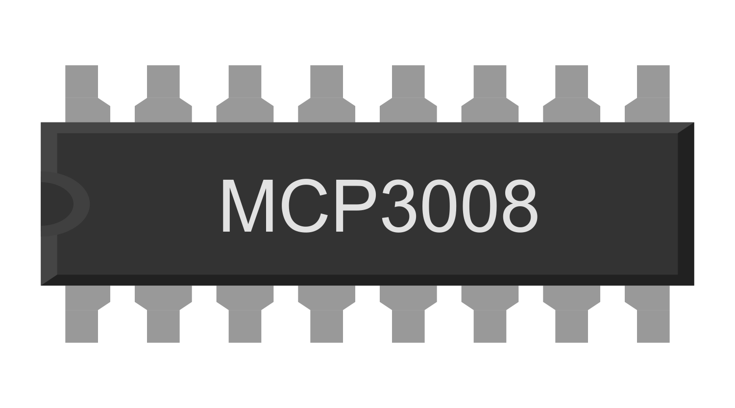
The MCP3008 is an 8-channel, 10-bit analog-to-digital converter (ADC) that allows for the conversion of analog signals into digital data. It communicates via the Serial Peripheral Interface (SPI), making it ideal for microcontroller applications where multiple analog inputs are required. This component is widely used in projects involving sensors, potentiometers, and other analog devices.
Explore Projects Built with MCP3008 8-channel 10-bit ADC


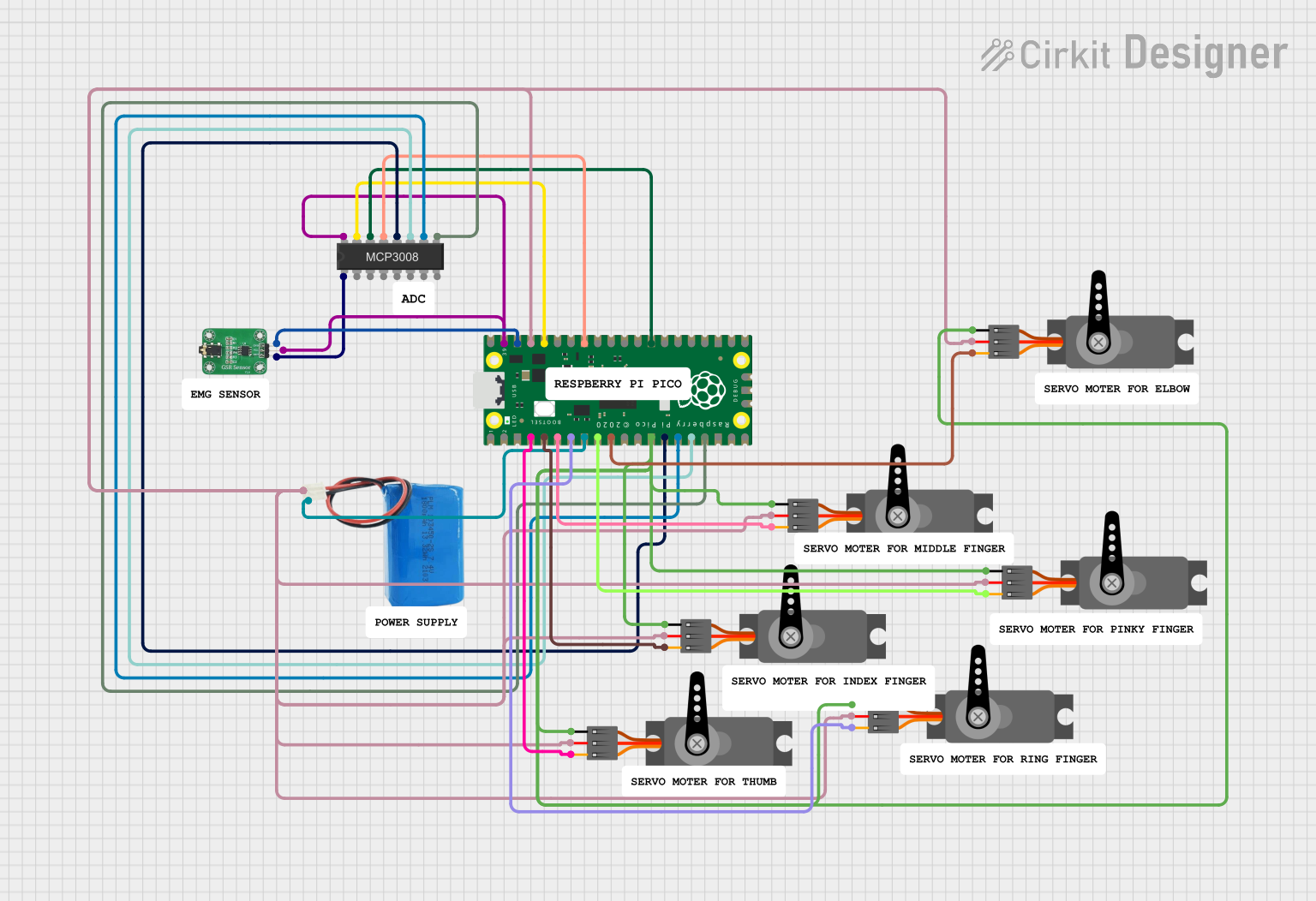
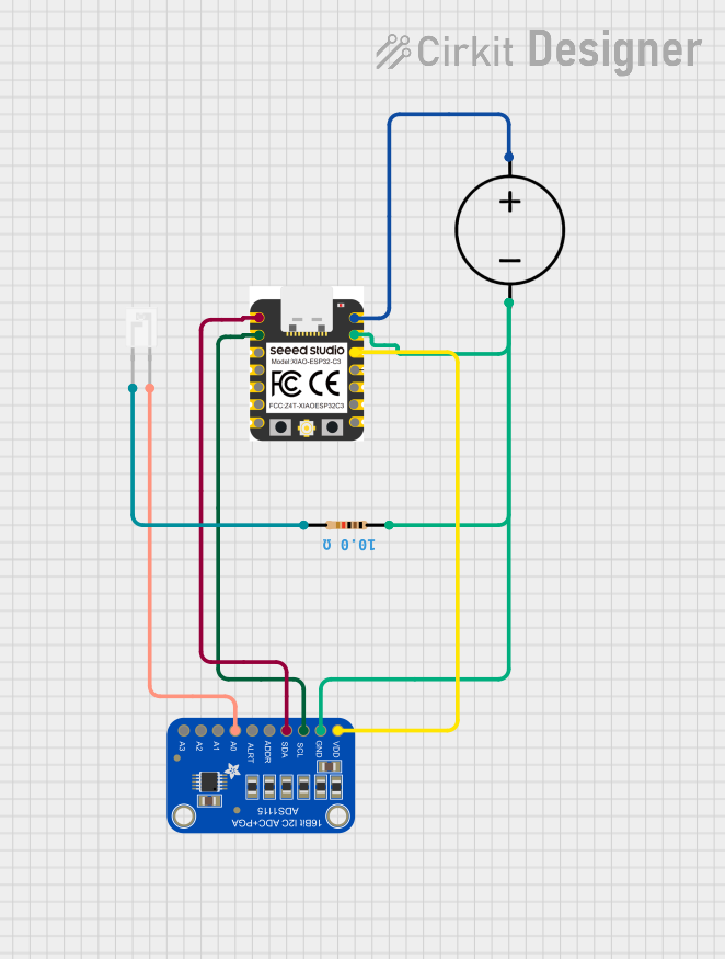
Explore Projects Built with MCP3008 8-channel 10-bit ADC
Common Applications and Use Cases
- Reading multiple analog sensors (e.g., temperature, light, or pressure sensors)
- Interfacing with microcontrollers like Arduino, Raspberry Pi, or ESP32
- Data acquisition systems
- Signal monitoring and processing
- Robotics and IoT applications
Technical Specifications
The MCP3008 is a versatile ADC with the following key specifications:
| Parameter | Value |
|---|---|
| Resolution | 10 bits |
| Number of Channels | 8 |
| Input Voltage Range | 0V to VREF (typically 5V or 3.3V) |
| Supply Voltage (VDD) | 2.7V to 5.5V |
| Communication Interface | SPI |
| Maximum Sampling Rate | 200 ksps (at 5V) |
| Power Consumption | 5 µA (typical, standby mode) |
| Package Types | PDIP, SOIC, TSSOP |
Pin Configuration and Descriptions
The MCP3008 has 16 pins, as described in the table below:
| Pin Number | Pin Name | Description |
|---|---|---|
| 1 | CH0 | Analog input channel 0 |
| 2 | CH1 | Analog input channel 1 |
| 3 | CH2 | Analog input channel 2 |
| 4 | CH3 | Analog input channel 3 |
| 5 | CH4 | Analog input channel 4 |
| 6 | CH5 | Analog input channel 5 |
| 7 | CH6 | Analog input channel 6 |
| 8 | CH7 | Analog input channel 7 |
| 9 | DGND | Digital ground |
| 10 | CS/SHDN | Chip select (active low) / Shutdown control |
| 11 | DIN | Data input (SPI MOSI) |
| 12 | DOUT | Data output (SPI MISO) |
| 13 | CLK | Clock input (SPI SCK) |
| 14 | AGND | Analog ground |
| 15 | VREF | Reference voltage for ADC (sets the input voltage range) |
| 16 | VDD | Positive supply voltage (2.7V to 5.5V) |
Usage Instructions
How to Use the MCP3008 in a Circuit
- Power Supply: Connect the VDD pin to a 3.3V or 5V power source, and connect the AGND and DGND pins to ground.
- Reference Voltage: Connect the VREF pin to the desired reference voltage (e.g., 3.3V or 5V). This determines the input voltage range for the ADC.
- SPI Connections:
- Connect the
CS/SHDNpin to a GPIO pin on your microcontroller to act as the chip select. - Connect the
DINpin to the SPI MOSI pin on your microcontroller. - Connect the
DOUTpin to the SPI MISO pin on your microcontroller. - Connect the
CLKpin to the SPI SCK pin on your microcontroller.
- Connect the
- Analog Inputs: Connect your analog signals to the CH0–CH7 pins. Ensure the input voltage does not exceed VREF.
- SPI Configuration: Configure your microcontroller's SPI interface to communicate with the MCP3008. The MCP3008 operates in SPI Mode 0 (CPOL = 0, CPHA = 0).
Example: Using MCP3008 with Arduino UNO
Below is an example of how to read an analog signal from channel 0 of the MCP3008 using an Arduino UNO:
#include <SPI.h>

// Define MCP3008 connections
const int CS_PIN = 10; // Chip Select pin connected to Arduino pin 10

void setup() {
  Serial.begin(9600); // Initialize serial communication
  SPI.begin();        // Initialize SPI communication
  pinMode(CS_PIN, OUTPUT); // Set CS pin as output
  digitalWrite(CS_PIN, HIGH); // Set CS pin high (inactive)
}

int readMCP3008(int channel) {
  // Ensure the channel is valid (0-7)
  if (channel < 0 || channel > 7) return -1;

  // Start SPI communication
  digitalWrite(CS_PIN, LOW); // Activate the MCP3008

  // Send start bit, single-ended mode, and channel selection
  byte command = 0b00000001; // Start bit
  byte config = (0b1000 | channel) << 4; // Single-ended mode + channel
  SPI.transfer(command); // Send start bit
  byte highByte = SPI.transfer(config); // Send config and receive high byte
  byte lowByte = SPI.transfer(0x00); // Receive low byte

  digitalWrite(CS_PIN, HIGH); // Deactivate the MCP3008

  // Combine high and low bytes into a 10-bit result
  int result = ((highByte & 0x03) << 8) | lowByte;
  return result;
}

void loop() {
  int value = readMCP3008(0); // Read from channel 0
  Serial.print("Channel 0 Value: ");
  Serial.println(value); // Print the ADC value
  delay(500); // Wait 500ms before the next reading
}
Important Considerations and Best Practices
- Voltage Levels: Ensure that the input voltage to the analog channels does not exceed VREF.
- Grounding: Connect both AGND and DGND to the same ground to avoid noise issues.
- Decoupling Capacitors: Place a 0.1 µF capacitor close to the VDD pin to stabilize the power supply.
- SPI Speed: Use an appropriate SPI clock speed to ensure reliable communication. For most applications, 1 MHz is sufficient.
Troubleshooting and FAQs
Common Issues and Solutions
No Data or Incorrect Readings:
- Verify the SPI connections (MOSI, MISO, SCK, and CS).
- Ensure the MCP3008 is powered correctly and the reference voltage is stable.
- Check that the SPI mode is set to Mode 0 (CPOL = 0, CPHA = 0).
Noise in Readings:
- Use proper grounding and shielding for analog signals.
- Add decoupling capacitors near the MCP3008 and the analog input sources.
All Channels Return Zero:
- Ensure the
CS/SHDNpin is being toggled correctly. - Verify that the analog input voltage is within the range of 0V to VREF.
- Ensure the
SPI Communication Fails:
- Check the SPI clock speed and reduce it if necessary.
- Ensure the microcontroller's SPI pins are correctly configured.
FAQs
Q: Can the MCP3008 be used with a 3.3V system?
A: Yes, the MCP3008 can operate with a supply voltage as low as 2.7V, making it compatible with 3.3V systems.
Q: What is the maximum input voltage for the analog channels?
A: The maximum input voltage is equal to the reference voltage (VREF), which is typically 3.3V or 5V.
Q: Can I use fewer than 8 channels?
A: Yes, you can use as many channels as needed. Unused channels can be left unconnected.
Q: How do I increase the resolution of the ADC?
A: The resolution of the MCP3008 is fixed at 10 bits. To achieve higher resolution, consider using a different ADC with higher resolution.