Cirkit Designer Logo
Cirkit Designer
Your all-in-one circuit design IDE
Home / 
Component Documentation

How to Use SparkFun gator:rtc: Examples, Pinouts, and Specs

Image of SparkFun gator:rtc
Cirkit Designer LogoDesign with SparkFun gator:rtc in Cirkit Designer

Introduction

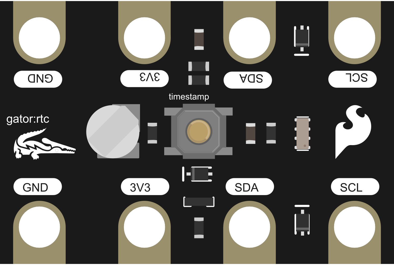
The SparkFun gator:rtc is a specialized real-time clock (RTC) breakout board designed for seamless integration with the micro:bit platform. This component provides accurate timekeeping and timestamp functionality, which is essential for applications that require time-sensitive operations. Common use cases include data logging with time stamps, creating clocks or timers, and managing scheduled events in educational projects or hobbyist applications.

Explore Projects Built with SparkFun gator:rtc

Use Cirkit Designer to design, explore, and prototype these projects online. Some projects support real-time simulation. Click "Open Project" to start designing instantly!
ESP32-Based Digital Clock with TFT Display and RTC Module
Image of Kello tft-näytöllä: A project utilizing SparkFun gator:rtc in a practical application
This circuit features an ESP32 microcontroller connected to an Adafruit TFT 1.8 inch display and a Real-Time Clock (RTC) module. The ESP32 is configured to communicate with the RTC to keep track of the current time and to control the display, which shows the time updated every second. The connections between the ESP32 and the peripherals facilitate data transfer for timekeeping and display purposes, with the ESP32 also providing power to the RTC.
Cirkit Designer LogoOpen Project in Cirkit Designer
Arduino UNO and Sim800l Battery-Powered Real-Time Clock with GSM Communication
Image of circuit1: A project utilizing SparkFun gator:rtc in a practical application
This circuit integrates an Arduino UNO with a DS3231 RTC module for real-time clock functionality and a Sim800l GSM module for communication. The Arduino is powered by a Li-ion battery and interfaces with the RTC via I2C, while the GSM module is connected for serial communication and powered through a resistor network.
Cirkit Designer LogoOpen Project in Cirkit Designer
ESP32-Powered Battery-Operated Real-Time Clock and TFT Display Module
Image of BHUMIKA PROJECT: A project utilizing SparkFun gator:rtc in a practical application
This circuit features an ESP32 microcontroller interfaced with a TFT LCD display and an RTC module, powered by a Type-C power bank module connected to a 3.7V battery. The ESP32 controls the display and reads time data from the RTC, making it suitable for applications requiring real-time clock functionality and visual output.
Cirkit Designer LogoOpen Project in Cirkit Designer
Arduino UNO-Based Smart Home Automation System with Bluetooth and RTC
Image of Pill Dispenser: A project utilizing SparkFun gator:rtc in a practical application
This circuit is a microcontroller-based system using an Arduino UNO to control various components including an RTC module, Bluetooth module, LCD display, pushbutton, buzzer, and multiple DC motors via motor drivers. The system is powered by a 5V adapter and is designed for real-time monitoring and control, with communication capabilities through Bluetooth and visual feedback via the LCD.
Cirkit Designer LogoOpen Project in Cirkit Designer

Explore Projects Built with SparkFun gator:rtc

Use Cirkit Designer to design, explore, and prototype these projects online. Some projects support real-time simulation. Click "Open Project" to start designing instantly!
Image of Kello tft-näytöllä: A project utilizing SparkFun gator:rtc in a practical application
ESP32-Based Digital Clock with TFT Display and RTC Module
This circuit features an ESP32 microcontroller connected to an Adafruit TFT 1.8 inch display and a Real-Time Clock (RTC) module. The ESP32 is configured to communicate with the RTC to keep track of the current time and to control the display, which shows the time updated every second. The connections between the ESP32 and the peripherals facilitate data transfer for timekeeping and display purposes, with the ESP32 also providing power to the RTC.
Cirkit Designer LogoOpen Project in Cirkit Designer
Image of circuit1: A project utilizing SparkFun gator:rtc in a practical application
Arduino UNO and Sim800l Battery-Powered Real-Time Clock with GSM Communication
This circuit integrates an Arduino UNO with a DS3231 RTC module for real-time clock functionality and a Sim800l GSM module for communication. The Arduino is powered by a Li-ion battery and interfaces with the RTC via I2C, while the GSM module is connected for serial communication and powered through a resistor network.
Cirkit Designer LogoOpen Project in Cirkit Designer
Image of BHUMIKA PROJECT: A project utilizing SparkFun gator:rtc in a practical application
ESP32-Powered Battery-Operated Real-Time Clock and TFT Display Module
This circuit features an ESP32 microcontroller interfaced with a TFT LCD display and an RTC module, powered by a Type-C power bank module connected to a 3.7V battery. The ESP32 controls the display and reads time data from the RTC, making it suitable for applications requiring real-time clock functionality and visual output.
Cirkit Designer LogoOpen Project in Cirkit Designer
Image of Pill Dispenser: A project utilizing SparkFun gator:rtc in a practical application
Arduino UNO-Based Smart Home Automation System with Bluetooth and RTC
This circuit is a microcontroller-based system using an Arduino UNO to control various components including an RTC module, Bluetooth module, LCD display, pushbutton, buzzer, and multiple DC motors via motor drivers. The system is powered by a 5V adapter and is designed for real-time monitoring and control, with communication capabilities through Bluetooth and visual feedback via the LCD.
Cirkit Designer LogoOpen Project in Cirkit Designer

Technical Specifications

Key Technical Details

  • IC Chip: Maxim Integrated DS3231 Real-Time Clock
  • Voltage: 3.3V (supplied by the micro:bit)
  • Battery Backup: CR1225 coin cell battery (not included)
  • Time Accuracy: ±2ppm from 0°C to +40°C
  • Communication: I2C interface

Pin Configuration and Descriptions

Pin Label Function Description
3V3 Power Connects to 3.3V power from the micro:bit
GND Ground Connects to ground on the micro:bit
SDA Data I2C data line, connects to micro:bit pin 20
SCL Clock I2C clock line, connects to micro:bit pin 19
INT Interrupt Optional interrupt pin, not used in basic operation

Usage Instructions

Integrating with micro:bit

  1. Connecting the gator:rtc: Use alligator clips to connect the 3V3 and GND pins on the gator:rtc to the corresponding 3.3V and GND pins on the micro:bit. Connect the SDA and SCL pins to pins 20 and 19 on the micro:bit, respectively.

  2. Coding with MakeCode: Open the Microsoft MakeCode editor for micro:bit and include the gator:rtc package. Use the blocks provided by the package to set and get the time.

  3. Using in a Circuit: When integrating the gator:rtc into a larger circuit, ensure that the I2C lines are not shared with other devices that might cause address conflicts.

Best Practices

  • Battery Installation: Install a CR1225 coin cell battery to maintain timekeeping during power loss.
  • Power Considerations: Ensure that the micro:bit is supplied with a stable 3.3V power source.
  • I2C Pull-up Resistors: The gator:rtc has built-in pull-up resistors for the I2C lines. Do not add additional pull-up resistors to these lines.

Troubleshooting and FAQs

Common Issues

  • Time Not Accurate: Ensure that the CR1225 battery is installed correctly and has sufficient charge.
  • Device Not Recognized: Check all connections, especially the I2C lines, for proper contact and continuity.
  • Intermittent Functionality: Make sure there are no loose connections and that the micro:bit is properly powered.

FAQs

  • Q: Can the gator:rtc be used with other microcontrollers?

    • A: Yes, it can be used with any microcontroller that supports I2C communication, but additional code libraries may be required.
  • Q: How long will the battery last?

    • A: The CR1225 battery can last for over a year, depending on the quality of the battery and the environmental conditions.
  • Q: What is the purpose of the INT pin?

    • A: The INT pin can be used for alarm interrupts, which are not covered in this basic documentation.

For further assistance, consult the SparkFun gator:rtc datasheet or contact SparkFun support.

Example Code for micro:bit

Below is an example code snippet for setting and reading the time on the gator:rtc using the micro:bit and MakeCode editor. This code assumes the inclusion of the gator:rtc package in the MakeCode editor.

// Initialize the gator:rtc and set the time to 12:00:00
gatorRTC.begin()
gatorRTC.setTime(12, 0, 0)

basic.forever(function () {
    // Read the current time from the gator:rtc
    let hours = gatorRTC.getHours()
    let minutes = gatorRTC.getMinutes()
    let seconds = gatorRTC.getSeconds()
    
    // Display the current time on the micro:bit's LED matrix
    basic.showString(hours + ":" + minutes + ":" + seconds)
})

Remember to wrap the code comments as needed to limit line length to 80 characters. This example provides a simple way to display the current time on the micro:bit's LED matrix.