
How to Use LMZ14203: Examples, Pinouts, and Specs
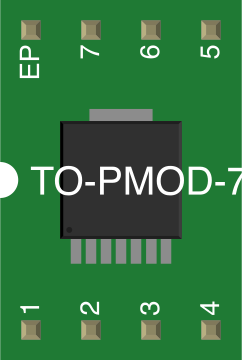
 Design with LMZ14203 in Cirkit Designer
Introduction
The LMZ14203 is a step-down (buck) voltage regulator designed to provide a compact and efficient solution for converting a higher input voltage to a lower output voltage. This integrated power module combines a DC-DC converter, inductor, and other necessary components into a single package, simplifying circuit design and reducing board space requirements.
Explore Projects Built with LMZ14203
 Open Project in Cirkit Designer
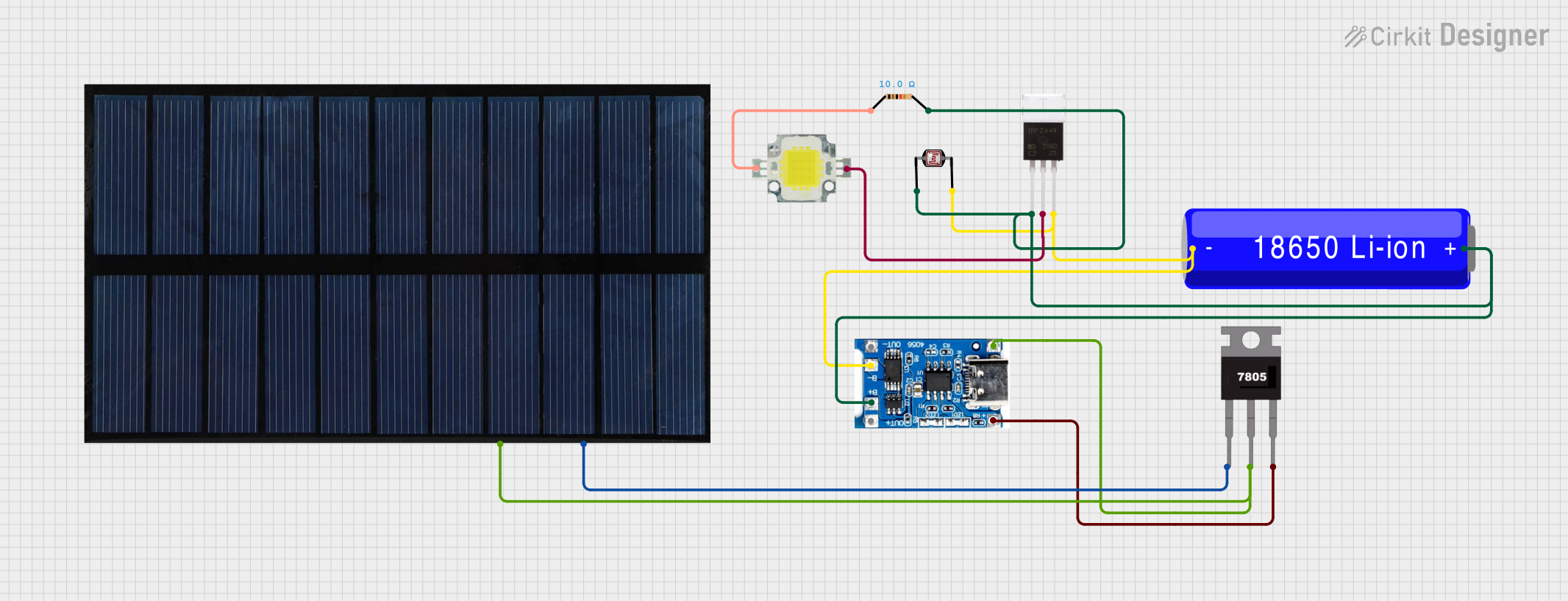 Open Project in Cirkit Designer
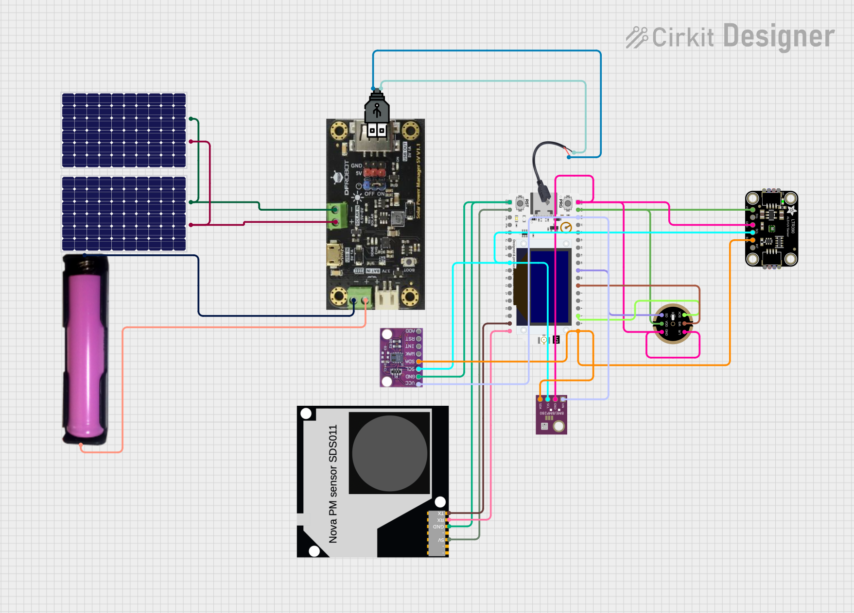 Open Project in Cirkit Designer
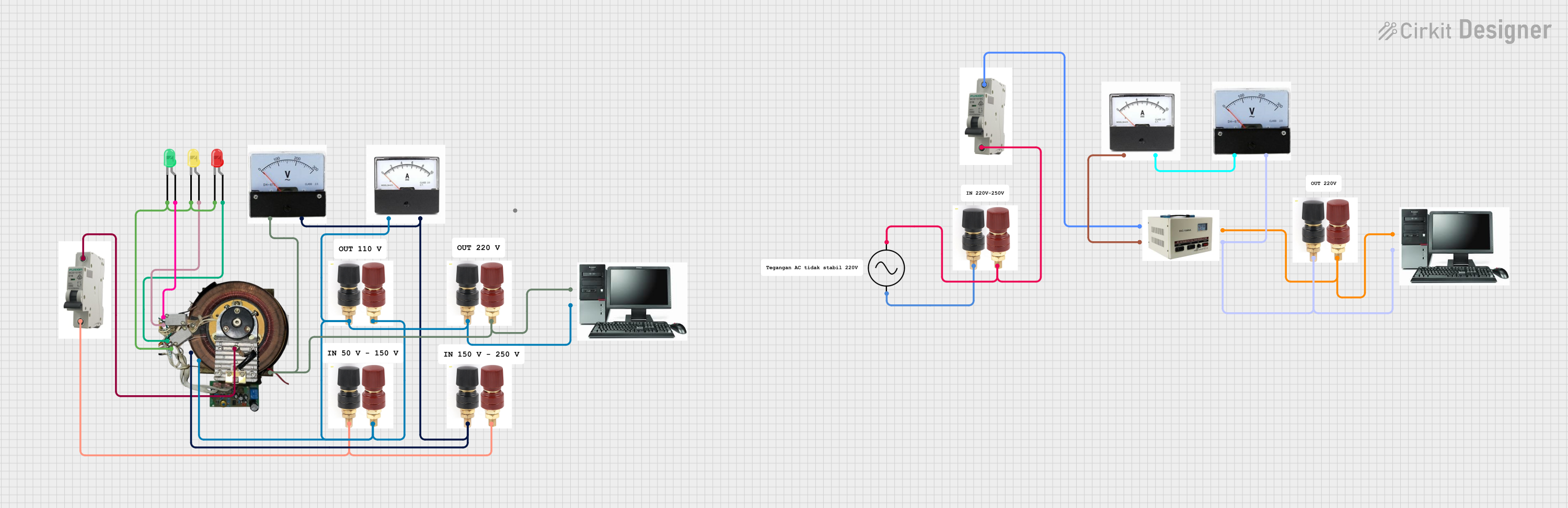 Open Project in Cirkit Designer
Explore Projects Built with LMZ14203
Open Project in Cirkit DesignerOpen Project in Cirkit DesignerOpen Project in Cirkit DesignerOpen Project in Cirkit DesignerCommon Applications and Use Cases
- Industrial and automotive power supplies
- Distributed power systems
- Battery-powered devices
- Point-of-load regulation for FPGAs, DSPs, and microcontrollers
- General-purpose voltage regulation in embedded systems
Technical Specifications
Key Technical Details
- Input Voltage Range: 6 V to 42 V
- Output Voltage Range: 0.8 V to 6 V (adjustable via external resistor)
- Output Current: Up to 3 A
- Efficiency: Up to 95% (depending on input/output voltage and load)
- Switching Frequency: 200 kHz to 1 MHz (adjustable)
- Operating Temperature Range: -40°C to +125°C
- Protection Features: Overcurrent protection, thermal shutdown, and undervoltage lockout (UVLO)
- Package: TO-PMOD-7 (7-pin Power Module)
Pin Configuration and Descriptions
The LMZ14203 has 7 pins, as described in the table below:
| Pin Number | Pin Name | Description |
|---|---|---|
| 1 | VIN | Input voltage pin. Connect to the input power supply (6 V to 42 V). |
| 2 | GND | Ground pin. Connect to the system ground. |
| 3 | VOUT | Regulated output voltage pin. Connect to the load. |
| 4 | FB | Feedback pin. Connect to a resistor divider to set the output voltage. |
| 5 | EN | Enable pin. Pull high to enable the regulator; pull low to disable it. |
| 6 | RT/CLK | Resistor timing or external clock input. Sets the switching frequency. |
| 7 | SS/TR | Soft-start or tracking pin. Connect a capacitor to control startup behavior. |
Usage Instructions
How to Use the LMZ14203 in a Circuit
- Input Voltage: Connect the VIN pin to a DC power source within the range of 6 V to 42 V. Use a decoupling capacitor (e.g., 10 µF ceramic) close to the VIN pin to reduce input noise.
- Output Voltage: Use a resistor divider network connected to the FB pin to set the desired output voltage. The output voltage can be calculated using the formula: [ V_{OUT} = 0.8 \times \left(1 + \frac{R_{TOP}}{R_{BOTTOM}}\right) ] where ( R_{TOP} ) and ( R_{BOTTOM} ) are the resistors in the divider.
- Enable Pin: Pull the EN pin high (e.g., connect to VIN through a resistor) to enable the regulator. Pull it low to disable the output.
- Switching Frequency: Connect a resistor to the RT/CLK pin to set the switching frequency. Refer to the datasheet for resistor values corresponding to specific frequencies.
- Soft-Start: Connect a capacitor to the SS/TR pin to control the startup time. A larger capacitor results in a slower startup.
- Output Capacitor: Place an appropriate output capacitor (e.g., 47 µF ceramic) close to the VOUT pin to stabilize the output voltage.
Important Considerations and Best Practices
- Ensure proper thermal management by using a PCB with adequate copper area under the LMZ14203 for heat dissipation.
- Use low-ESR capacitors for input and output filtering to improve performance.
- Keep the feedback resistor divider and other sensitive traces as short as possible to minimize noise.
- Follow the recommended layout guidelines in the datasheet to ensure stable operation.
Example: Connecting the LMZ14203 to an Arduino UNO
The LMZ14203 can be used to power an Arduino UNO by stepping down a higher voltage (e.g., 12 V) to 5 V. Below is an example circuit and Arduino code to demonstrate its use:
Circuit Connections
- Connect a 12 V DC power supply to the VIN pin of the LMZ14203.
- Set the output voltage to 5 V by selecting appropriate feedback resistors.
- Connect the VOUT pin to the 5 V pin of the Arduino UNO.
- Connect the GND pin of the LMZ14203 to the GND pin of the Arduino UNO.
Arduino Code Example
// Example code to blink an LED using the Arduino UNO powered by the LMZ14203
// The LMZ14203 provides a stable 5 V output to the Arduino UNO.

const int ledPin = 13; // Pin connected to the onboard LED

void setup() {
  pinMode(ledPin, OUTPUT); // Set the LED pin as an output
}

void loop() {
  digitalWrite(ledPin, HIGH); // Turn the LED on
  delay(1000);                // Wait for 1 second
  digitalWrite(ledPin, LOW);  // Turn the LED off
  delay(1000);                // Wait for 1 second
}
Troubleshooting and FAQs
Common Issues and Solutions
No Output Voltage:
- Ensure the EN pin is pulled high to enable the regulator.
- Check the input voltage; it must be within the 6 V to 42 V range.
- Verify the feedback resistor values and connections.
Output Voltage is Incorrect:
- Double-check the resistor divider network connected to the FB pin.
- Ensure the output capacitor is properly connected and has the correct value.
Overheating:
- Verify that the load current does not exceed 3 A.
- Improve thermal dissipation by increasing the copper area on the PCB.
High Output Ripple:
- Use low-ESR capacitors for input and output filtering.
- Minimize the length of high-current traces to reduce noise.
FAQs
Q: Can the LMZ14203 operate without a soft-start capacitor?
A: Yes, the LMZ14203 can operate without a soft-start capacitor, but the startup behavior will be faster and may cause inrush current. Adding a capacitor to the SS/TR pin is recommended for smoother startup.
Q: What is the maximum switching frequency of the LMZ14203?
A: The LMZ14203 supports a maximum switching frequency of 1 MHz, which can be set using an external resistor on the RT/CLK pin.
Q: Can the LMZ14203 be synchronized to an external clock?
A: Yes, the RT/CLK pin can accept an external clock signal for synchronization. Refer to the datasheet for details on clock signal requirements.
Q: Is the LMZ14203 suitable for battery-powered applications?
A: Yes, the LMZ14203 is highly efficient and suitable for battery-powered applications, provided the input voltage is within the specified range.