How to Use CD74HC4067: Examples, Pinouts, and Specs
Introduction
The CD74HC4067 is a 16-channel analog multiplexer/demultiplexer manufactured by Arduino with the part ID "Leonardo." This versatile component allows the selection of one of 16 input signals to be routed to a single output line (or vice versa). It is designed to handle both analog and digital signals, making it ideal for a wide range of applications.
Explore Projects Built with CD74HC4067


Explore Projects Built with CD74HC4067
Common Applications and Use Cases
- Expanding the number of analog or digital inputs/outputs in microcontroller projects
- Signal routing in audio systems
- Sensor data acquisition
- Multiplexing/demultiplexing in communication systems
- Analog-to-digital conversion (ADC) channel expansion
Technical Specifications
The CD74HC4067 is a high-speed CMOS device with the following key specifications:
| Parameter | Value |
|---|---|
| Supply Voltage (Vcc) | 2V to 6V |
| Input Voltage Range | 0V to Vcc |
| Maximum Current per Pin | ±25mA |
| Power Dissipation | 500mW |
| Propagation Delay | ~10ns (at 5V) |
| Operating Temperature Range | -55°C to +125°C |
| Package Type | DIP-24, SOIC-24, TSSOP-24 |
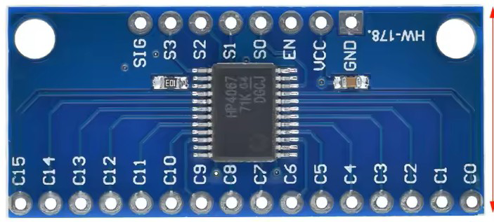
Pin Configuration and Descriptions
The CD74HC4067 has 24 pins, as described in the table below:
| Pin Number | Pin Name | Description |
|---|---|---|
| 1-4 | S0-S3 | Address selection pins (used to select one of the 16 channels) |
| 5-20 | CH0-CH15 | Channel pins (16 input/output channels) |
| 21 | EN | Enable pin (active LOW; must be LOW for the device to function) |
| 22 | Z | Common I/O pin (connected to the selected channel) |
| 23 | Vcc | Positive power supply |
| 24 | GND | Ground |
Usage Instructions
The CD74HC4067 is straightforward to use in both analog and digital circuits. Below are the steps and considerations for using this component:
Connecting the CD74HC4067
- Power Supply: Connect the Vcc pin to a voltage source (2V to 6V) and the GND pin to ground.
- Channel Selection: Use the S0-S3 pins to select one of the 16 channels. The binary value on these pins determines the active channel:
- For example, if S0-S3 =
0000, CH0 is selected; if S0-S3 =1111, CH15 is selected.
- For example, if S0-S3 =
- Enable Pin: Ensure the EN pin is set to LOW to enable the device. If EN is HIGH, all channels are disconnected.
- Signal Routing: Connect the signal source to the desired channel pin (CH0-CH15) and the output device to the Z pin.
Important Considerations
- Voltage Levels: Ensure that the input signal voltage does not exceed the supply voltage (Vcc).
- Impedance Matching: For analog signals, consider the impedance of the connected devices to minimize signal loss.
- Noise Reduction: Use decoupling capacitors (e.g., 0.1µF) near the Vcc pin to reduce noise and improve stability.
Example: Using CD74HC4067 with Arduino UNO
The following example demonstrates how to use the CD74HC4067 to read multiple analog sensors with an Arduino UNO:
// Example: Reading multiple analog sensors using CD74HC4067 and Arduino UNO

// Define the address selection pins (S0-S3) connected to Arduino digital pins
const int S0 = 2;
const int S1 = 3;
const int S2 = 4;
const int S3 = 5;

// Define the common I/O pin (Z) connected to Arduino analog pin
const int Z = A0;

void setup() {
  // Set address selection pins as outputs
  pinMode(S0, OUTPUT);
  pinMode(S1, OUTPUT);
  pinMode(S2, OUTPUT);
  pinMode(S3, OUTPUT);

  // Initialize serial communication for debugging
  Serial.begin(9600);
}

void loop() {
  for (int channel = 0; channel < 16; channel++) {
    // Set the address pins to select the desired channel
    digitalWrite(S0, channel & 0x01); // Set S0 to the least significant bit
    digitalWrite(S1, (channel >> 1) & 0x01); // Set S1 to the second bit
    digitalWrite(S2, (channel >> 2) & 0x01); // Set S2 to the third bit
    digitalWrite(S3, (channel >> 3) & 0x01); // Set S3 to the most significant bit

    // Read the analog value from the selected channel
    int sensorValue = analogRead(Z);

    // Print the channel number and sensor value to the Serial Monitor
    Serial.print("Channel ");
    Serial.print(channel);
    Serial.print(": ");
    Serial.println(sensorValue);

    delay(500); // Wait for 500ms before reading the next channel
  }
}
Notes:
- Connect the S0-S3 pins to Arduino digital pins (e.g., D2-D5).
- Connect the Z pin to an Arduino analog input pin (e.g., A0).
- Connect the CH0-CH15 pins to the sensors or input devices.
Troubleshooting and FAQs
Common Issues
No Signal Output:
- Ensure the EN pin is set to LOW.
- Verify that the S0-S3 pins are correctly configured to select the desired channel.
Signal Distortion:
- Check that the input signal voltage is within the specified range (0V to Vcc).
- Use decoupling capacitors to reduce noise.
Incorrect Channel Selection:
- Double-check the binary values on the S0-S3 pins.
- Ensure there are no loose or incorrect connections.
FAQs
Q: Can the CD74HC4067 handle both analog and digital signals?
A: Yes, the CD74HC4067 is designed to handle both analog and digital signals, making it highly versatile.
Q: What happens if the EN pin is HIGH?
A: When the EN pin is HIGH, all channels are disconnected, and no signal is routed to the Z pin.
Q: Can I use the CD74HC4067 with a 3.3V microcontroller?
A: Yes, the CD74HC4067 operates with a supply voltage as low as 2V, making it compatible with 3.3V systems.
Q: How do I prevent crosstalk between channels?
A: To minimize crosstalk, ensure proper grounding and use shielded cables for sensitive analog signals.