Cirkit Designer Logo
Cirkit Designer
Your all-in-one circuit design IDE
Home / 
Component Documentation

How to Use Screw Terminal Block Breakout: Examples, Pinouts, and Specs

Image of Screw Terminal Block Breakout
Cirkit Designer LogoDesign with Screw Terminal Block Breakout in Cirkit Designer

Introduction

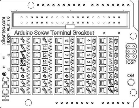
The Screw Terminal Block Breakout Module HD024 by HCDC is a versatile and practical component used in electronic circuits. It provides an easy and secure way to connect wires to a circuit board without soldering. This breakout module is commonly used in prototyping, testing, and permanent installations where connections may need to be reconfigured or maintained over time.

Explore Projects Built with Screw Terminal Block Breakout

Use Cirkit Designer to design, explore, and prototype these projects online. Some projects support real-time simulation. Click "Open Project" to start designing instantly!
Peltier-Controlled Thermal Management System with SPST Switch
Image of Mini car refrigerator circuit: A project utilizing Screw Terminal Block Breakout in a practical application
This circuit consists of multiple Peltier modules and fans connected in parallel to a digital power supply, with a rocker switch (SPST) controlling the power flow to one of the Peltier modules and multiple fans. The 2.1mm Barrel Jack with Terminal Block serves as the power input connector, and the rocker switch allows for selective enabling or disabling of the connected devices. The circuit is designed to provide cooling or heating through the Peltier modules while the fans assist in heat dissipation or air circulation.
Cirkit Designer LogoOpen Project in Cirkit Designer
Modular Power Distribution System with Multiple SMPS Units and 120V Outlet
Image of Cellion-Tesla: A project utilizing Screw Terminal Block Breakout in a practical application
This circuit is designed to convert 240V AC power to both 12V and 24V DC outputs using multiple SMPS units. Terminal blocks are used to organize and distribute the power, while a 120V outlet provides additional AC power access. The circuit is likely used for powering various electronic devices that require different voltage levels.
Cirkit Designer LogoOpen Project in Cirkit Designer
Arduino Mega 2560 Hall Sensor Interface for Real-Time Magnetic Field Detection
Image of Hall Effect CD: A project utilizing Screw Terminal Block Breakout in a practical application
This circuit uses an Arduino Mega 2560 to read data from a Hall Sensor, which is powered through a terminal block connected to the Arduino's 5V supply. The sensor's ground is connected to the Arduino's ground, and its signal output is read by the Arduino on pin D2.
Cirkit Designer LogoOpen Project in Cirkit Designer
Battery-Powered Relay Control System with Directional Switch
Image of Skema Lampu D2: A project utilizing Screw Terminal Block Breakout in a practical application
This circuit involves a 12V battery powering a relay system controlled by a directional switch. The relays are connected through terminal blocks and are used to switch between different outputs, indicated by the AdaGator Top components.
Cirkit Designer LogoOpen Project in Cirkit Designer

Explore Projects Built with Screw Terminal Block Breakout

Use Cirkit Designer to design, explore, and prototype these projects online. Some projects support real-time simulation. Click "Open Project" to start designing instantly!
Image of Mini car refrigerator circuit: A project utilizing Screw Terminal Block Breakout in a practical application
Peltier-Controlled Thermal Management System with SPST Switch
This circuit consists of multiple Peltier modules and fans connected in parallel to a digital power supply, with a rocker switch (SPST) controlling the power flow to one of the Peltier modules and multiple fans. The 2.1mm Barrel Jack with Terminal Block serves as the power input connector, and the rocker switch allows for selective enabling or disabling of the connected devices. The circuit is designed to provide cooling or heating through the Peltier modules while the fans assist in heat dissipation or air circulation.
Cirkit Designer LogoOpen Project in Cirkit Designer
Image of Cellion-Tesla: A project utilizing Screw Terminal Block Breakout in a practical application
Modular Power Distribution System with Multiple SMPS Units and 120V Outlet
This circuit is designed to convert 240V AC power to both 12V and 24V DC outputs using multiple SMPS units. Terminal blocks are used to organize and distribute the power, while a 120V outlet provides additional AC power access. The circuit is likely used for powering various electronic devices that require different voltage levels.
Cirkit Designer LogoOpen Project in Cirkit Designer
Image of Hall Effect CD: A project utilizing Screw Terminal Block Breakout in a practical application
Arduino Mega 2560 Hall Sensor Interface for Real-Time Magnetic Field Detection
This circuit uses an Arduino Mega 2560 to read data from a Hall Sensor, which is powered through a terminal block connected to the Arduino's 5V supply. The sensor's ground is connected to the Arduino's ground, and its signal output is read by the Arduino on pin D2.
Cirkit Designer LogoOpen Project in Cirkit Designer
Image of Skema Lampu D2: A project utilizing Screw Terminal Block Breakout in a practical application
Battery-Powered Relay Control System with Directional Switch
This circuit involves a 12V battery powering a relay system controlled by a directional switch. The relays are connected through terminal blocks and are used to switch between different outputs, indicated by the AdaGator Top components.
Cirkit Designer LogoOpen Project in Cirkit Designer

Common Applications and Use Cases

  • Prototyping electronic circuits
  • Industrial control systems
  • Robotics and automation
  • DIY electronics projects
  • Educational platforms for electronics learning

Technical Specifications

Key Technical Details

  • Rated Voltage: Up to 250V
  • Rated Current: Up to 3A per terminal
  • Terminal Pitch: 5.08mm
  • Wire Gauge Compatibility: 26-16 AWG
  • Number of Terminals: Varies by model (commonly 2, 3, 4, 6, 8, etc.)
  • Mounting Options: Through-hole PCB mounting
  • Material: Flame retardant plastic with metal screws and contacts

Pin Configuration and Descriptions

Pin Number Description Notes
1 Terminal 1 Connect to wire from source 1
2 Terminal 2 Connect to wire from source 2
... ... ...
N Terminal N Connect to wire from source N
GND Ground Terminal Connect to system ground

Note: The pin configuration may vary based on the specific model of the breakout module.

Usage Instructions

How to Use the Component in a Circuit

  1. Wire Insertion: Strip the end of the wire to be connected, typically around 5-7mm of insulation removed.
  2. Securing Wires: Insert the stripped wire end into the corresponding terminal hole and tighten the screw to secure the wire.
  3. Connecting to a Circuit: The other side of the breakout module will have pins or pads that can be soldered directly to a PCB or connected to a breadboard.
  4. Testing Connections: Ensure all connections are secure and test the circuit for continuity before applying power.

Important Considerations and Best Practices

  • Do not exceed the rated voltage and current specifications.
  • Ensure that all screws are tightened to a firm fit but avoid over-tightening which can damage the wire or terminal.
  • Use wires that are within the compatible gauge range to ensure a secure connection.
  • Periodically check and retighten the screws if necessary, especially in environments with vibration or thermal cycling.

Troubleshooting and FAQs

Common Issues Users Might Face

  • Loose Connections: If a wire becomes loose, it can cause intermittent or failed connections. Check and retighten the screws if necessary.
  • Stripped Screws: Over-tightening can strip the screws, making it difficult to secure the wires. If this happens, the terminal block may need to be replaced.
  • Incorrect Wiring: Ensure that the wiring matches the circuit design to prevent short circuits or incorrect functionality.

Solutions and Tips for Troubleshooting

  • Continuity Testing: Use a multimeter to check for continuity in the connections. This can help identify loose or broken wires.
  • Visual Inspection: Regularly inspect the terminal block for any signs of damage or wear.
  • Proper Wire Stripping: Use a wire stripper to remove insulation and avoid damaging the wire conductor.

FAQs

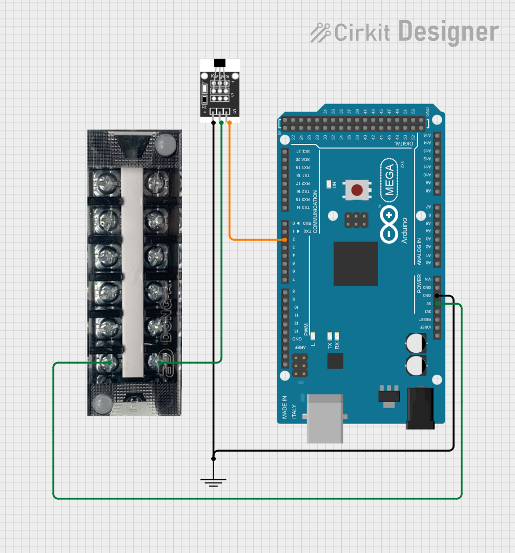
Q: Can I use the Screw Terminal Block Breakout with an Arduino UNO? A: Yes, the breakout can be used with an Arduino UNO or any other microcontroller by connecting the breakout pins to the appropriate I/O pins on the Arduino.

Q: What is the maximum wire size that can be used with the HD024? A: The HD024 can accommodate wire sizes from 26 to 16 AWG.

Q: How do I know if my connection is secure? A: A secure connection will hold the wire firmly in place without any movement. You can gently tug on the wire to ensure it is not loose.

Example Arduino UNO Connection Code

// Example code to demonstrate how to set up a digital output
// to an LED connected through the Screw Terminal Block Breakout HD024

void setup() {
  pinMode(13, OUTPUT); // Set digital pin 13 as an output
}

void loop() {
  digitalWrite(13, HIGH); // Turn on the LED
  delay(1000);           // Wait for 1 second
  digitalWrite(13, LOW);  // Turn off the LED
  delay(1000);           // Wait for 1 second
}

// Note: Connect the anode of the LED to digital pin 13 through the
// Screw Terminal Block Breakout and the cathode to GND with a suitable
// resistor in series to limit current.

Note: The above code is a simple blink example. The actual implementation will depend on the specific application and the rest of the circuit connected to the Screw Terminal Block Breakout.

This documentation provides a comprehensive guide to using the HD024 Screw Terminal Block Breakout Module. For further assistance or technical support, please contact HCDC customer service.