Cirkit Designer Logo
Cirkit Designer
Your all-in-one circuit design IDE
Home / 
Component Documentation

How to Use QTR-1A Reflectance Sensor : Examples, Pinouts, and Specs

Image of QTR-1A Reflectance Sensor
Cirkit Designer LogoDesign with QTR-1A Reflectance Sensor in Cirkit Designer

Introduction

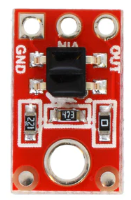
The QTR-1A is an infrared reflectance sensor designed for detecting the presence of objects or measuring distances by emitting infrared light and sensing the reflected light. This compact and efficient sensor is widely used in robotics applications, such as line-following robots, edge detection, and obstacle avoidance systems. Its small size and low power consumption make it an excellent choice for embedded systems and microcontroller-based projects.

Explore Projects Built with QTR-1A Reflectance Sensor

Use Cirkit Designer to design, explore, and prototype these projects online. Some projects support real-time simulation. Click "Open Project" to start designing instantly!
Arduino Nano-Powered PID Line Following Robot with Reflectance Sensor Array and Dual Motor Driver
Image of Line following bot: A project utilizing QTR-1A Reflectance Sensor  in a practical application
This circuit is designed for an advanced line-following robot that uses a QTRX-HD-07RC Reflectance Sensor Array for line sensing and a Motor Driver 1A Dual TB6612FNG to control two DC Mini Metal Gear Motors. The Arduino Nano serves as the microcontroller, running a PID control algorithm to adjust the motor speeds for precise tracking. Power is supplied by a 5V battery for the logic and a 12V battery for the motor driver.
Cirkit Designer LogoOpen Project in Cirkit Designer
Arduino UNO and AS7262 Color Change Detection System with Bluetooth and OLED Display
Image of CAR project: A project utilizing QTR-1A Reflectance Sensor  in a practical application
This circuit is designed to detect color changes in a solution using a spectral sensor, time the change, provide a sound cue via a piezo buzzer, and send the timing data to a computer via a Bluetooth module. The Arduino UNO microcontroller coordinates the sensor readings, timing, and communication, while an OLED display and NeoPixel ring provide visual feedback.
Cirkit Designer LogoOpen Project in Cirkit Designer
ESP32-Based Environmental Monitoring System with Gas Sensors and OLED Display
Image of EnviroXpert Pro: A project utilizing QTR-1A Reflectance Sensor  in a practical application
This circuit is an environmental monitoring system using an ESP32 microcontroller. It integrates various sensors, including the MQ-7 and MQ135 gas sensors, ENS160+AHT21 air quality and temperature/humidity sensor, and a KY-037 microphone, to collect environmental data. The data is displayed on a 1.3" OLED screen.
Cirkit Designer LogoOpen Project in Cirkit Designer
Battery-Powered Smart Light with Proximity Sensor and OLED Display using Adafruit QT Py RP2040
Image of lab: A project utilizing QTR-1A Reflectance Sensor  in a practical application
This circuit is a portable, battery-powered system featuring an Adafruit QT Py RP2040 microcontroller that interfaces with an OLED display, a proximity sensor, an accelerometer, and an RGB LED strip. The system is powered by a lithium-ion battery with a step-up boost converter to provide 5V for the LED strip, and it includes a toggle switch for power control. The microcontroller communicates with the sensors and display via I2C.
Cirkit Designer LogoOpen Project in Cirkit Designer

Explore Projects Built with QTR-1A Reflectance Sensor

Use Cirkit Designer to design, explore, and prototype these projects online. Some projects support real-time simulation. Click "Open Project" to start designing instantly!
Image of Line following bot: A project utilizing QTR-1A Reflectance Sensor  in a practical application
Arduino Nano-Powered PID Line Following Robot with Reflectance Sensor Array and Dual Motor Driver
This circuit is designed for an advanced line-following robot that uses a QTRX-HD-07RC Reflectance Sensor Array for line sensing and a Motor Driver 1A Dual TB6612FNG to control two DC Mini Metal Gear Motors. The Arduino Nano serves as the microcontroller, running a PID control algorithm to adjust the motor speeds for precise tracking. Power is supplied by a 5V battery for the logic and a 12V battery for the motor driver.
Cirkit Designer LogoOpen Project in Cirkit Designer
Image of CAR project: A project utilizing QTR-1A Reflectance Sensor  in a practical application
Arduino UNO and AS7262 Color Change Detection System with Bluetooth and OLED Display
This circuit is designed to detect color changes in a solution using a spectral sensor, time the change, provide a sound cue via a piezo buzzer, and send the timing data to a computer via a Bluetooth module. The Arduino UNO microcontroller coordinates the sensor readings, timing, and communication, while an OLED display and NeoPixel ring provide visual feedback.
Cirkit Designer LogoOpen Project in Cirkit Designer
Image of EnviroXpert Pro: A project utilizing QTR-1A Reflectance Sensor  in a practical application
ESP32-Based Environmental Monitoring System with Gas Sensors and OLED Display
This circuit is an environmental monitoring system using an ESP32 microcontroller. It integrates various sensors, including the MQ-7 and MQ135 gas sensors, ENS160+AHT21 air quality and temperature/humidity sensor, and a KY-037 microphone, to collect environmental data. The data is displayed on a 1.3" OLED screen.
Cirkit Designer LogoOpen Project in Cirkit Designer
Image of lab: A project utilizing QTR-1A Reflectance Sensor  in a practical application
Battery-Powered Smart Light with Proximity Sensor and OLED Display using Adafruit QT Py RP2040
This circuit is a portable, battery-powered system featuring an Adafruit QT Py RP2040 microcontroller that interfaces with an OLED display, a proximity sensor, an accelerometer, and an RGB LED strip. The system is powered by a lithium-ion battery with a step-up boost converter to provide 5V for the LED strip, and it includes a toggle switch for power control. The microcontroller communicates with the sensors and display via I2C.
Cirkit Designer LogoOpen Project in Cirkit Designer

Common Applications

  • Line-following robots
  • Edge detection in robotic systems
  • Obstacle detection and avoidance
  • Proximity sensing
  • Position tracking in automation systems

Technical Specifications

The QTR-1A Reflectance Sensor is a simple yet powerful component. Below are its key technical details:

Key Technical Details

  • Operating Voltage: 3.3V to 5V
  • Current Consumption: ~25 mA
  • Output Type: Analog voltage (proportional to reflectance)
  • IR Emitter Wavelength: 940 nm
  • Optimal Sensing Distance: 3 mm to 6 mm
  • Maximum Sensing Distance: ~25 mm (depending on surface reflectivity)
  • Dimensions: 0.5" × 0.3" × 0.1" (13 mm × 8 mm × 3 mm)

Pin Configuration and Descriptions

The QTR-1A sensor has three pins, as described in the table below:

Pin Name Description
1 VCC Power supply input (3.3V to 5V). Connect to the positive terminal of the power.
2 GND Ground. Connect to the ground of the power supply.
3 OUT Analog output. Provides a voltage proportional to the reflectance detected.

Usage Instructions

The QTR-1A Reflectance Sensor is straightforward to use in a circuit. Follow the steps below to integrate it into your project:

Connecting the Sensor

  1. Power Supply: Connect the VCC pin to a 3.3V or 5V power source and the GND pin to the ground.
  2. Output Signal: Connect the OUT pin to an analog input pin of your microcontroller (e.g., Arduino UNO).
  3. Placement: Position the sensor 3 mm to 6 mm above the surface for optimal performance. Ensure the sensor faces the surface directly.

Important Considerations

  • Surface Reflectivity: The sensor's output depends on the reflectivity of the surface. Dark surfaces (e.g., black lines) reflect less IR light, resulting in a lower output voltage, while bright surfaces (e.g., white lines) reflect more IR light, producing a higher output voltage.
  • Ambient Light: Minimize ambient IR light interference by shielding the sensor or using it in controlled lighting conditions.
  • Calibration: Calibrate the sensor for your specific application to determine the threshold values for detecting different surfaces.

Example: Using QTR-1A with Arduino UNO

Below is an example of how to use the QTR-1A sensor with an Arduino UNO to read reflectance values:

// QTR-1A Reflectance Sensor Example with Arduino UNO
// Connect the OUT pin of the QTR-1A to A0 on the Arduino UNO

const int sensorPin = A0; // Analog pin connected to the QTR-1A OUT pin
int sensorValue = 0;      // Variable to store the sensor reading

void setup() {
  Serial.begin(9600); // Initialize serial communication at 9600 baud
}

void loop() {
  sensorValue = analogRead(sensorPin); // Read the analog value from the sensor
  Serial.print("Sensor Value: ");
  Serial.println(sensorValue); // Print the sensor value to the Serial Monitor

  delay(100); // Delay for 100 ms before the next reading
}

Best Practices

  • Use a stable power supply to avoid fluctuations in sensor readings.
  • Mount the sensor securely to prevent movement during operation.
  • Test the sensor in your specific environment to fine-tune its placement and calibration.

Troubleshooting and FAQs

Common Issues and Solutions

  1. No Output or Incorrect Readings:

    • Ensure the sensor is powered correctly (3.3V to 5V).
    • Verify all connections are secure and correct.
    • Check for damage to the sensor or wiring.
  2. Inconsistent Readings:

    • Reduce ambient IR light interference by shielding the sensor.
    • Ensure the sensor is positioned at the recommended distance from the surface.
  3. Low Sensitivity:

    • Clean the sensor to remove dust or debris.
    • Verify the surface reflectivity is within the sensor's detectable range.
  4. Output Always High or Low:

    • Check if the surface is too reflective or too dark for the sensor to detect.
    • Adjust the sensor's distance from the surface.

FAQs

Q: Can the QTR-1A detect colors?
A: No, the QTR-1A is designed to detect reflectance, not specific colors. It differentiates surfaces based on their reflectivity to infrared light.

Q: What is the maximum sensing distance?
A: The sensor can detect reflectance up to ~25 mm, but optimal performance is achieved at 3 mm to 6 mm.

Q: Can I use the QTR-1A with a 3.3V microcontroller?
A: Yes, the QTR-1A operates at both 3.3V and 5V, making it compatible with 3.3V microcontrollers.

Q: How do I calibrate the sensor?
A: Use the sensor to measure the reflectance of the surfaces in your application and determine threshold values for detection. Adjust your code accordingly.

By following this documentation, you can effectively integrate the QTR-1A Reflectance Sensor into your projects and troubleshoot any issues that arise.