The YBX-BMI088 is a compact, high-performance 9-axis motion sensor manufactured by YI Board. It integrates a 3-axis accelerometer, a 3-axis gyroscope, and a 3-axis magnetometer into a single package, enabling precise motion tracking and orientation detection. This sensor is widely used in applications such as robotics, drones, wearable devices, and gaming controllers, where accurate motion sensing is critical.
Explore Projects Built with YBX-BMI088
Use Cirkit Designer to design, explore, and prototype these projects online. Some projects support real-time simulation. Click "Open Project" to start designing instantly!
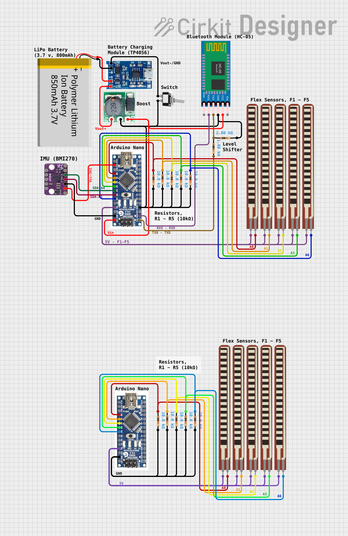
This circuit features an Arduino Nano interfaced with an HC-05 Bluetooth module, a BMI160 6DOF sensor, and multiple flex resistors. It is powered by a polymer lithium-ion battery through a lipo battery charger module and a step-up boost converter. The primary function appears to be wireless sensor data collection and transmission, with the flex resistors possibly serving as input devices and the accelerometer/gyro for motion tracking.
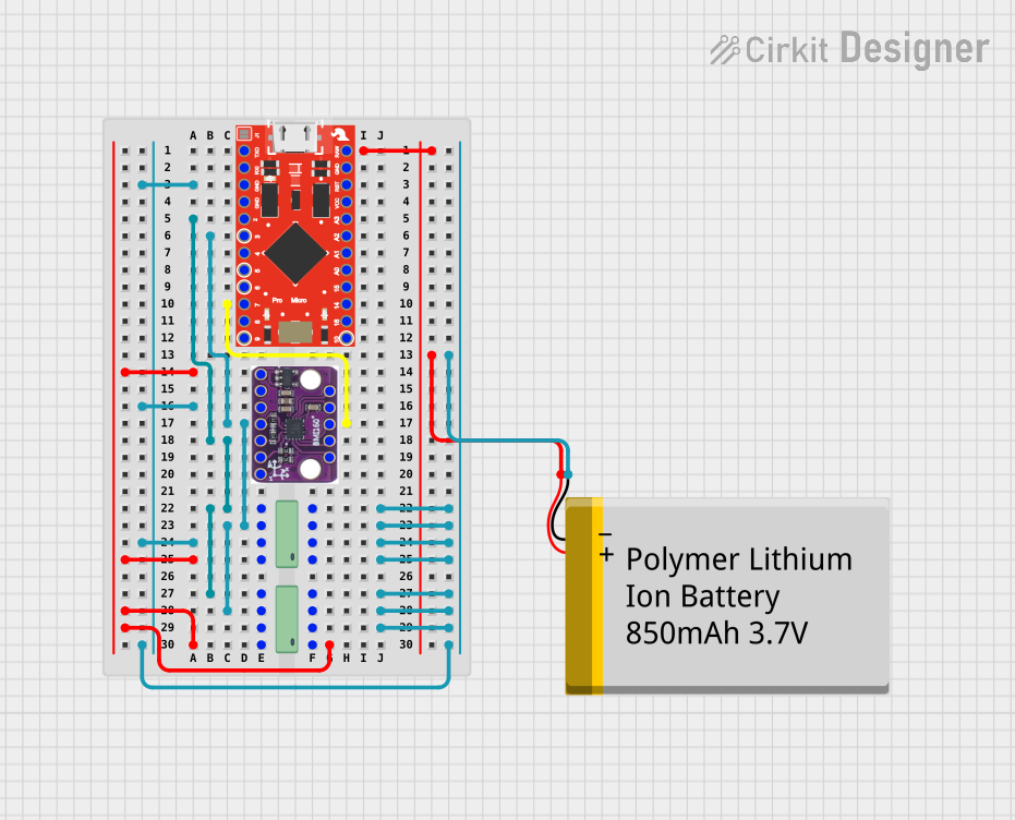
This circuit is designed for motion sensing and data logging applications. It features a SparkFun Pro Micro microcontroller interfaced with a BMI160 6DOF sensor for motion detection and two 24LC512 EEPROM chips for extended data storage. The microcontroller reads gyroscopic and accelerometer data from the BMI160 sensor, processes it, and stores it in the EEPROM, with power supplied by a Polymer Lithium Ion Battery.
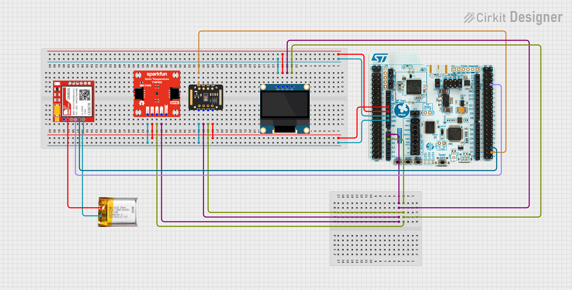
This circuit is a multi-sensor data acquisition system that uses a Nucleo WB55RG microcontroller to interface with a digital temperature sensor (TMP102), a pulse oximeter and heart-rate sensor (MAX30102), and a 0.96" OLED display via I2C. Additionally, it includes a Sim800l module for GSM communication, powered by a 3.7V LiPo battery.
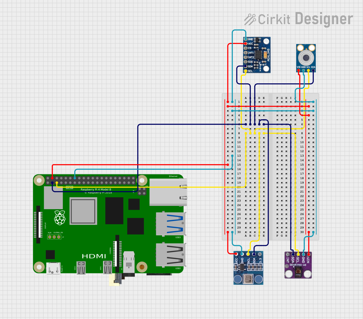
This circuit integrates multiple sensors, including an accelerometer (ADXL345), a barometric pressure sensor (BMP180), a pulse oximeter (max30100), and an infrared temperature sensor (mlx90614), all interfaced with a Raspberry Pi 4B via I2C communication. The Raspberry Pi serves as the central processing unit, collecting and processing data from the sensors for various applications such as health monitoring and environmental sensing.
The following table outlines the key technical specifications of the YBX-BMI088:
Parameter
Value
Supply Voltage
2.4V to 3.6V
Accelerometer Range
±2g, ±4g, ±8g, ±16g
Gyroscope Range
±125°/s, ±250°/s, ±500°/s, ±2000°/s
Magnetometer Range
±4900 µT
Communication Interface
I2C, SPI
Operating Temperature
-40°C to +85°C
Power Consumption
0.9 mA (typical, accelerometer)
Package Dimensions
3.0 mm x 4.5 mm x 0.95 mm
Pin Configuration and Descriptions
The YBX-BMI088 has the following pin configuration:
Pin Number
Pin Name
Description
1
VDD
Power supply (2.4V to 3.6V)
2
GND
Ground
3
SDA/SDI
I2C data line / SPI data input
4
SCL/SCK
I2C clock line / SPI clock input
5
CS
Chip select for SPI
6
INT1
Interrupt 1 output
7
INT2
Interrupt 2 output
8
DRDY
Data ready signal
Usage Instructions
How to Use the YBX-BMI088 in a Circuit
Power Supply: Connect the VDD pin to a 3.3V power source and the GND pin to ground.
Communication Interface: Choose between I2C or SPI for communication:
For I2C, connect the SDA and SCL pins to the corresponding I2C lines on your microcontroller.
For SPI, connect the SDI, SCK, and CS pins to the SPI lines on your microcontroller.
Interrupts: Use the INT1 and INT2 pins to handle interrupts for specific events like data ready or motion detection.
Pull-Up Resistors: If using I2C, ensure pull-up resistors (typically 4.7kΩ) are connected to the SDA and SCL lines.
Important Considerations and Best Practices
Power Supply Stability: Use a decoupling capacitor (e.g., 0.1 µF) near the VDD pin to ensure stable power.
Orientation: Mount the sensor on the PCB in the correct orientation for accurate readings.
Calibration: Perform sensor calibration (e.g., offset and sensitivity adjustment) for optimal performance.
Data Filtering: Use filtering techniques to reduce noise in accelerometer, gyroscope, and magnetometer data.
Example Code for Arduino UNO
Below is an example of how to interface the YBX-BMI088 with an Arduino UNO using the I2C interface:
#include <Wire.h>

// Define the I2C address of the YBX-BMI088
#define BMI088_I2C_ADDRESS 0x68

void setup() {
  Wire.begin(); // Initialize I2C communication
  Serial.begin(9600); // Initialize serial communication for debugging

  // Configure the YBX-BMI088
  Wire.beginTransmission(BMI088_I2C_ADDRESS);
  Wire.write(0x7E); // Register to reset the sensor
  Wire.write(0xB6); // Reset command
  Wire.endTransmission();
  delay(100); // Wait for the sensor to reset

  Serial.println("YBX-BMI088 initialized.");
}

void loop() {
  // Request accelerometer data
  Wire.beginTransmission(BMI088_I2C_ADDRESS);
  Wire.write(0x12); // Register address for accelerometer data
  Wire.endTransmission();
  Wire.requestFrom(BMI088_I2C_ADDRESS, 6); // Request 6 bytes (X, Y, Z)

  if (Wire.available() == 6) {
    int16_t accelX = (Wire.read() << 8) | Wire.read();
    int16_t accelY = (Wire.read() << 8) | Wire.read();
    int16_t accelZ = (Wire.read() << 8) | Wire.read();

    // Print accelerometer data
    Serial.print("Accel X: "); Serial.print(accelX);
    Serial.print(" Y: "); Serial.print(accelY);
    Serial.print(" Z: "); Serial.println(accelZ);
  }

  delay(500); // Delay for readability
}
Troubleshooting and FAQs
Common Issues and Solutions
No Data from the Sensor:
Ensure the sensor is powered correctly (check VDD and GND connections).
Verify the I2C or SPI connections and ensure the correct address is used.
Check for proper pull-up resistors on the I2C lines.
Inaccurate Readings:
Perform calibration to account for offsets and sensitivity variations.
Ensure the sensor is mounted securely to avoid vibrations affecting readings.
Communication Errors:
Double-check the wiring and ensure no loose connections.
Verify that the microcontroller's I2C or SPI clock speed is compatible with the sensor.
FAQs
Q: Can the YBX-BMI088 operate at 5V?
A: No, the YBX-BMI088 operates within a supply voltage range of 2.4V to 3.6V. Use a voltage regulator if your system operates at 5V.
Q: How do I select between I2C and SPI?
A: The communication interface is selected based on how the SDA/SDI and SCL/SCK pins are connected. Refer to the datasheet for detailed configuration.
Q: Is the sensor waterproof?
A: No, the YBX-BMI088 is not waterproof. Protect it from moisture in outdoor or humid environments.
Q: Can I use this sensor for GPS applications?
A: While the YBX-BMI088 provides motion and orientation data, it does not include GPS functionality. It can, however, complement a GPS module for navigation systems.


 Open Project in Cirkit Designer