How to Use huskylense: Examples, Pinouts, and Specs
Introduction
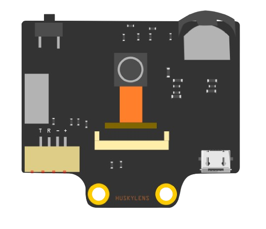
HuskyLens is an AI-powered camera module capable of recognizing objects, faces, colors, and more. It is designed to simplify the integration of AI vision into projects, making it an excellent choice for robotics, automation, and interactive systems. With built-in machine learning algorithms, HuskyLens can perform tasks such as object tracking, facial recognition, and line following without requiring external processing. Its user-friendly interface and compatibility with microcontrollers like Arduino and Raspberry Pi make it a versatile tool for both beginners and advanced users.
Explore Projects Built with huskylense
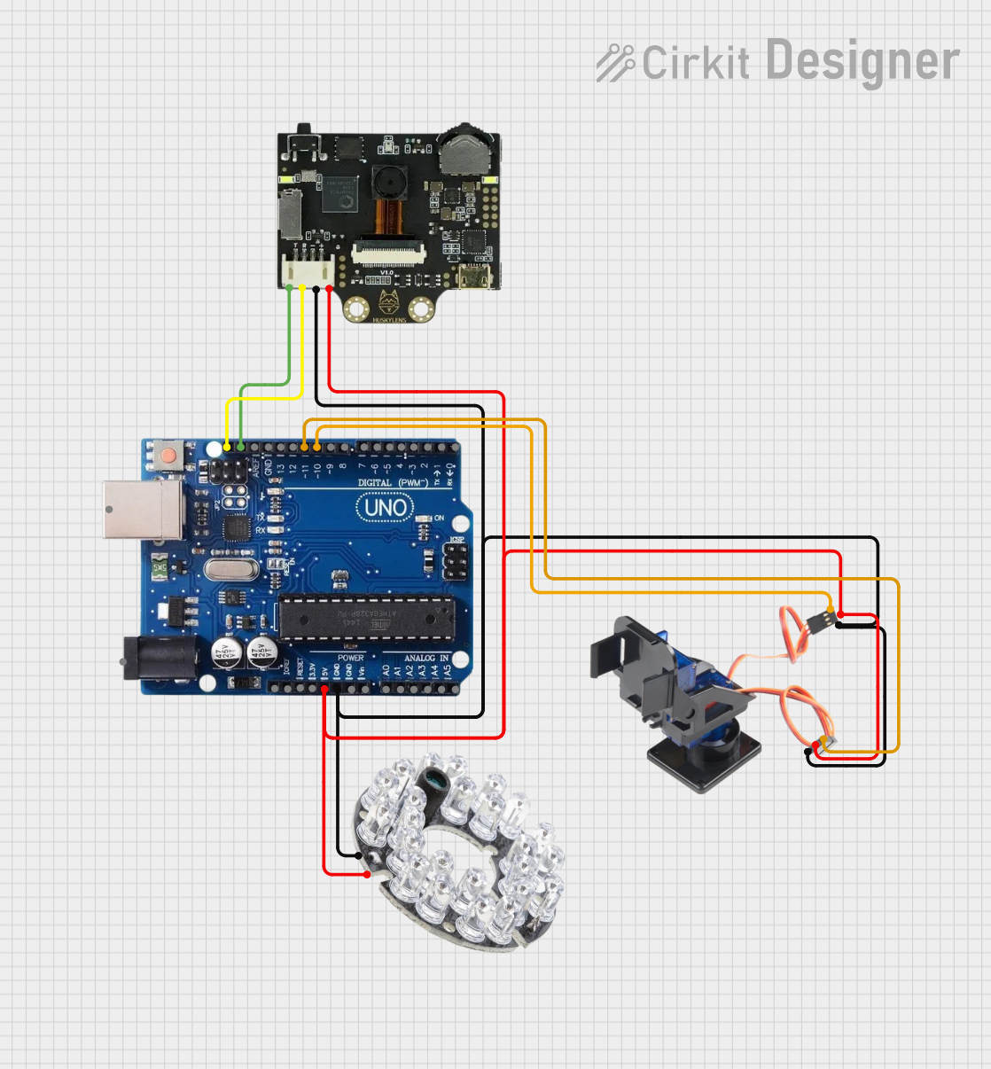
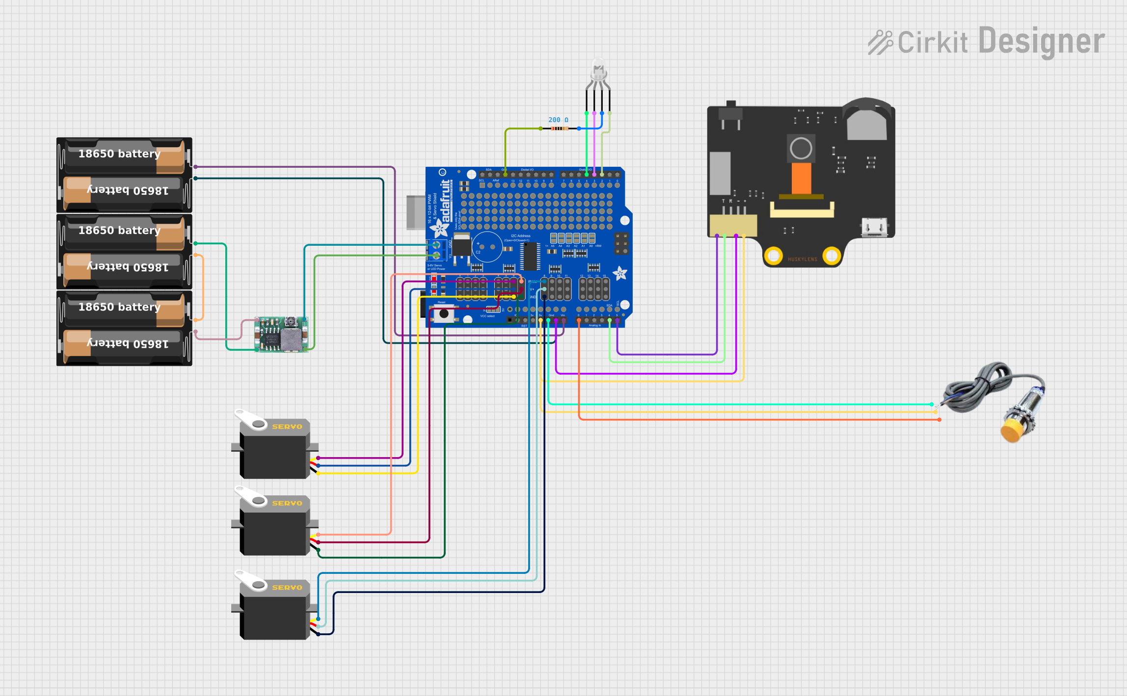
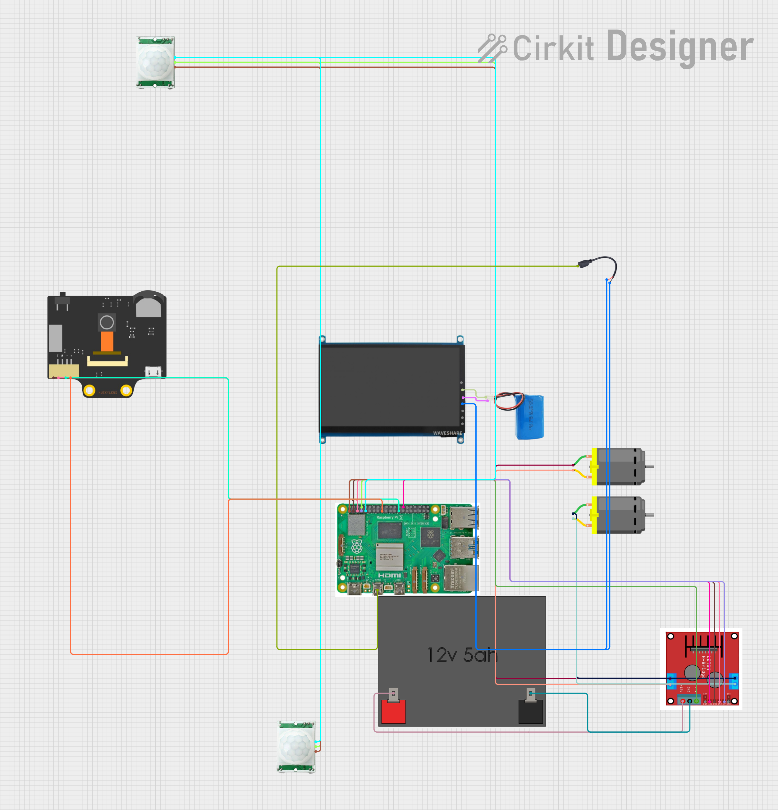
Explore Projects Built with huskylense
Common Applications and Use Cases
- Robotics: Object detection, line following, and obstacle avoidance.
- Automation: Facial recognition for access control or smart home systems.
- Education: Teaching AI and computer vision concepts.
- Interactive projects: Gesture recognition and color-based interactions.
Technical Specifications
Key Technical Details
- Processor: Kendryte K210 AI chip.
- Display: 2.0-inch IPS screen for real-time feedback.
- Power Supply: 3.3V to 5V DC.
- Communication Interfaces: UART, I2C.
- Recognition Capabilities: Object detection, face recognition, line following, color recognition, tag (QR code) recognition, and object classification.
- Storage: Built-in memory for saving learned models.
- Dimensions: 52mm x 44mm x 20mm.
- Weight: Approximately 30g.
Pin Configuration and Descriptions
The HuskyLens module has a 4-pin interface for communication and power. Below is the pin configuration:
| Pin | Name | Description |
|---|---|---|
| 1 | VCC | Power input (3.3V to 5V DC). |
| 2 | GND | Ground connection. |
| 3 | TX | UART Transmit pin (used for serial communication). |
| 4 | RX | UART Receive pin (used for serial communication). |
For I2C communication, the module uses the following pins:
| Pin | Name | Description |
|---|---|---|
| 3 | SCL | I2C Clock Line (shared with TX pin in UART mode). |
| 4 | SDA | I2C Data Line (shared with RX pin in UART mode). |
Usage Instructions
How to Use the Component in a Circuit
- Power the Module: Connect the VCC pin to a 3.3V or 5V power source and the GND pin to ground.
- Choose Communication Protocol: Decide whether to use UART or I2C for communication with your microcontroller.
- For UART: Connect the TX pin of HuskyLens to the RX pin of the microcontroller, and the RX pin of HuskyLens to the TX pin of the microcontroller.
- For I2C: Connect the SCL and SDA pins to the corresponding I2C pins on the microcontroller.
- Initialize Communication: Use the appropriate library or code to establish communication with the HuskyLens module.
- Select a Function: Use the onboard buttons or send commands via the microcontroller to select a specific AI function (e.g., object recognition, face recognition).
- Train the Module: Point the camera at the object or face you want to recognize and press the "Learn" button on the module.
- Integrate into Your Project: Use the data from the HuskyLens to control other components in your project, such as motors, LEDs, or servos.
Important Considerations and Best Practices
- Ensure the module is powered within the specified voltage range (3.3V to 5V) to avoid damage.
- Use a stable power supply to prevent communication errors or unexpected behavior.
- When using I2C, ensure the pull-up resistors are properly configured on the SCL and SDA lines.
- Avoid exposing the camera lens to direct sunlight or reflective surfaces, as this may affect recognition accuracy.
- Regularly update the firmware to access new features and improvements.
Example Code for Arduino UNO
Below is an example of how to use HuskyLens with an Arduino UNO via I2C communication:
#include <Wire.h> // Include the Wire library for I2C communication

#define HUSKYLENS_I2C_ADDRESS 0x32 // Default I2C address for HuskyLens

void setup() {
  Wire.begin(); // Initialize I2C communication
  Serial.begin(9600); // Initialize serial communication for debugging

  // Send initialization command to HuskyLens
  Wire.beginTransmission(HUSKYLENS_I2C_ADDRESS);
  Wire.write(0x55); // Example command to initialize HuskyLens
  Wire.write(0xAA); // Example command to confirm initialization
  Wire.endTransmission();

  Serial.println("HuskyLens initialized.");
}

void loop() {
  // Request data from HuskyLens
  Wire.requestFrom(HUSKYLENS_I2C_ADDRESS, 6); // Request 6 bytes of data
  if (Wire.available()) {
    Serial.print("Data received: ");
    while (Wire.available()) {
      byte data = Wire.read(); // Read each byte
      Serial.print(data, HEX); // Print data in hexadecimal format
      Serial.print(" ");
    }
    Serial.println();
  }

  delay(500); // Wait for 500ms before the next request
}
Notes on the Code
- The example code initializes the HuskyLens module and requests data via I2C.
- Replace the initialization commands (
0x55and0xAA) with the appropriate commands for your specific use case. - Use the HuskyLens Arduino library for more advanced functionality and simplified commands.
Troubleshooting and FAQs
Common Issues and Solutions
HuskyLens Not Powering On
- Cause: Insufficient or incorrect power supply.
- Solution: Ensure the VCC pin is connected to a 3.3V or 5V power source and the GND pin is properly grounded.
No Data Received from HuskyLens
- Cause: Incorrect communication protocol or wiring.
- Solution: Double-check the connections for UART or I2C. Ensure the correct pins are connected and the communication protocol is properly initialized in the code.
Recognition Accuracy is Low
- Cause: Poor lighting conditions or improper training.
- Solution: Ensure the camera is in a well-lit environment and retrain the module with clear and focused images of the object or face.
Module Freezes or Becomes Unresponsive
- Cause: Firmware issue or unstable power supply.
- Solution: Restart the module and ensure a stable power source. Update the firmware to the latest version.
FAQs
Can HuskyLens recognize multiple objects simultaneously? Yes, HuskyLens can recognize and track multiple objects depending on the selected function.
Is HuskyLens compatible with Raspberry Pi? Yes, HuskyLens can be used with Raspberry Pi via UART or I2C communication.
How do I update the firmware? Connect the HuskyLens module to your computer via USB and use the official HuskyLens software to update the firmware.
What is the maximum recognition distance? The recognition distance depends on the object size and lighting conditions but typically ranges from 0.5m to 2m.
By following this documentation, you can effectively integrate HuskyLens into your projects and leverage its AI capabilities for a wide range of applications.