How to Use CN3791 MPPT board: Examples, Pinouts, and Specs
Introduction
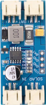
The CN3791 MPPT (Maximum Power Point Tracking) board is designed to optimize the power output from solar panels by dynamically adjusting the electrical load. This ensures that the maximum power is extracted from the solar panel under varying environmental conditions, such as changes in sunlight intensity or temperature. The board is highly efficient and compact, making it ideal for renewable energy projects.
Explore Projects Built with CN3791 MPPT board
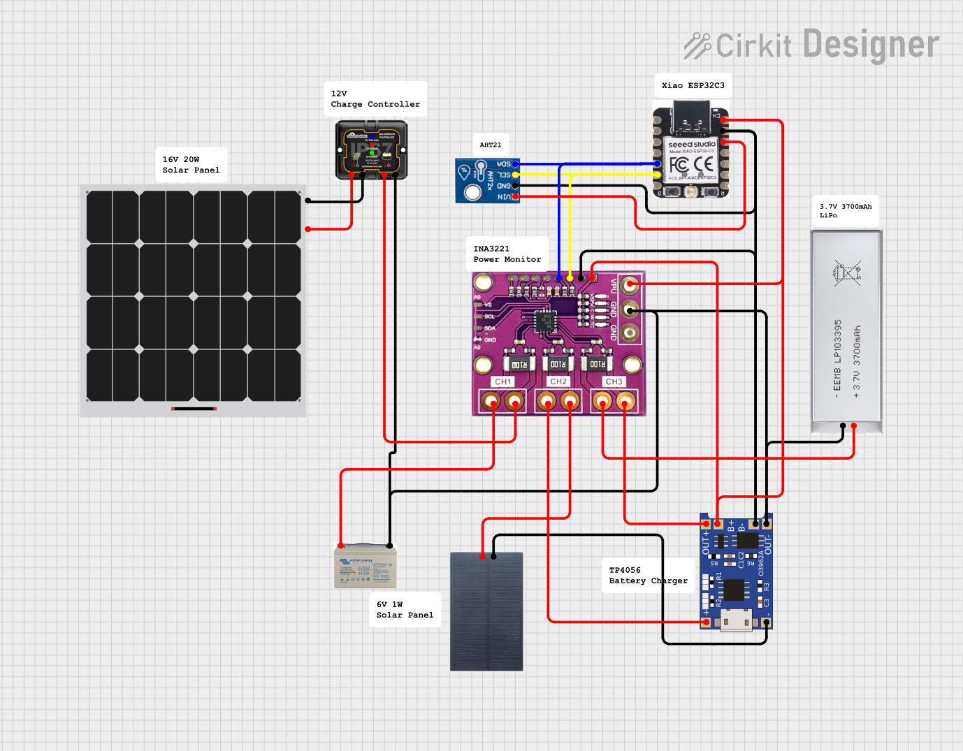
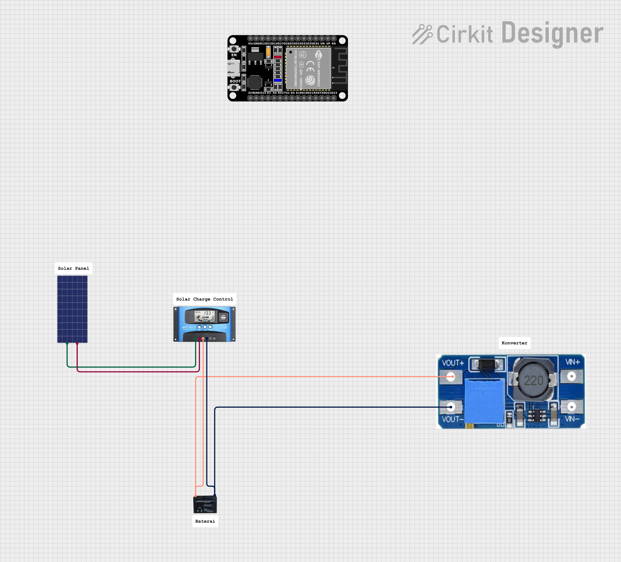
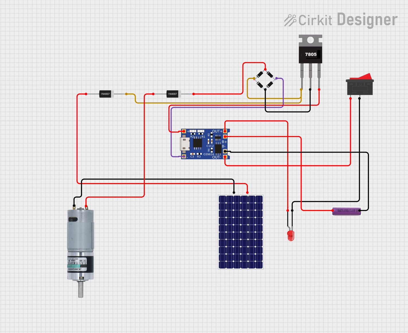
Explore Projects Built with CN3791 MPPT board
Common Applications and Use Cases
- Solar-powered battery charging systems
- Off-grid renewable energy setups
- IoT devices powered by solar panels
- Portable solar chargers
- Educational and experimental renewable energy projects
Technical Specifications
The CN3791 MPPT board is built around the CN3791 IC, which is specifically designed for solar charging applications. Below are the key technical details:
Key Specifications
| Parameter | Value |
|---|---|
| Input Voltage Range | 4.5V to 28V |
| Output Voltage Range | Configurable (based on battery) |
| Maximum Charging Current | 3A |
| Efficiency | Up to 95% |
| MPPT Tracking Accuracy | ±1% |
| Operating Temperature Range | -40°C to +85°C |
| Supported Battery Types | Lithium-ion, LiFePO4 |
Pin Configuration and Descriptions
| Pin Name | Description |
|---|---|
| VIN | Input voltage from the solar panel (4.5V to 28V). |
| GND | Ground connection. |
| BAT | Battery positive terminal connection. |
| PROG | Used to set the charging current via an external resistor. |
| STAT1 | Status indicator pin (charging status). |
| STAT2 | Status indicator pin (fully charged or fault status). |
| TEMP | Temperature sensing pin for battery protection (optional). |
| CE | Chip enable pin (active high to enable the IC). |
Usage Instructions
How to Use the CN3791 MPPT Board in a Circuit
- Connect the Solar Panel: Attach the positive and negative terminals of the solar panel to the
VINandGNDpins, respectively. - Connect the Battery: Connect the positive terminal of the battery to the
BATpin and the negative terminal toGND. - Set the Charging Current: Use an external resistor on the
PROGpin to set the desired charging current. Refer to the datasheet for the resistor value calculation. - Monitor Status: Use the
STAT1andSTAT2pins to monitor the charging status. These pins can be connected to LEDs for visual indication. - Optional Temperature Sensing: If required, connect a thermistor to the
TEMPpin for battery temperature monitoring and protection.
Important Considerations and Best Practices
- Ensure that the input voltage from the solar panel is within the specified range (4.5V to 28V).
- Match the output voltage configuration to the battery type (e.g., 4.2V for Li-ion, 3.6V for LiFePO4).
- Use appropriate heat dissipation methods if the board operates at high currents for extended periods.
- Avoid short-circuiting the
BATpin to prevent damage to the board or battery. - For Arduino-based projects, the
STAT1andSTAT2pins can be connected to digital input pins for status monitoring.
Example Arduino Code for Monitoring Status
// Define pins connected to STAT1 and STAT2
const int stat1Pin = 2; // STAT1 connected to digital pin 2
const int stat2Pin = 3; // STAT2 connected to digital pin 3

void setup() {
  pinMode(stat1Pin, INPUT); // Set STAT1 as input
  pinMode(stat2Pin, INPUT); // Set STAT2 as input
  Serial.begin(9600);       // Initialize serial communication
}

void loop() {
  int stat1 = digitalRead(stat1Pin); // Read STAT1 pin
  int stat2 = digitalRead(stat2Pin); // Read STAT2 pin

  // Interpret and display charging status
  if (stat1 == LOW && stat2 == HIGH) {
    Serial.println("Battery is charging...");
  } else if (stat1 == HIGH && stat2 == LOW) {
    Serial.println("Battery is fully charged.");
  } else if (stat1 == HIGH && stat2 == HIGH) {
    Serial.println("No battery connected or fault detected.");
  } else {
    Serial.println("Unknown status.");
  }

  delay(1000); // Wait for 1 second before checking again
}
Troubleshooting and FAQs
Common Issues and Solutions
No Output Voltage on BAT Pin:
- Cause: Input voltage is too low or not connected.
- Solution: Ensure the solar panel provides at least 4.5V and is properly connected.
Overheating of the Board:
- Cause: Excessive charging current or poor heat dissipation.
- Solution: Reduce the charging current by adjusting the resistor on the
PROGpin or improve heat dissipation with a heatsink.
Battery Not Charging:
- Cause: Incorrect battery connection or configuration.
- Solution: Verify the battery is connected correctly and the output voltage matches the battery type.
STAT1 and STAT2 LEDs Not Lighting Up:
- Cause: Faulty connections or damaged board.
- Solution: Check the connections and ensure the board is functioning properly.
FAQs
Q: Can the CN3791 MPPT board charge multiple batteries in series?
A: No, the board is designed to charge a single battery. For multiple batteries, use a battery management system (BMS).
Q: Is the board compatible with lead-acid batteries?
A: No, the CN3791 is optimized for lithium-ion and LiFePO4 batteries only.
Q: How do I calculate the resistor value for the PROG pin?
A: Refer to the CN3791 datasheet for the formula: R_PROG = 1000 / I_CHG, where I_CHG is the desired charging current in amperes.
Q: Can I use the board without a solar panel?
A: Yes, you can use a DC power supply within the input voltage range (4.5V to 28V) as an alternative to a solar panel.