How to Use Actuator Hall effect: Examples, Pinouts, and Specs
Introduction
The Actuator Hall Effect sensor, manufactured by TRU Components (Part ID: TC-13492796), is a precise and reliable device designed to detect magnetic fields and convert them into electrical signals. This component leverages the Hall effect principle, making it ideal for applications requiring non-contact position sensing, speed detection, or proximity sensing.
Common applications include:
- Automotive systems (e.g., throttle position sensing, gear detection)
- Industrial automation (e.g., motor control, conveyor belt monitoring)
- Consumer electronics (e.g., rotary encoders, joysticks)
- Robotics (e.g., wheel speed sensing, actuator feedback)
Explore Projects Built with Actuator Hall effect

Explore Projects Built with Actuator Hall effect
Technical Specifications
The following table outlines the key technical details of the TC-13492796 Actuator Hall Effect sensor:
| Parameter | Value |
|---|---|
| Supply Voltage (Vcc) | 3.3V to 24V |
| Output Voltage | 0.4V (low) to Vcc (high) |
| Output Type | Digital (open-drain or push-pull) |
| Operating Current | 5 mA (typical) |
| Magnetic Sensitivity | ±5 mT to ±50 mT |
| Operating Temperature | -40°C to +125°C |
| Response Time | <10 µs |
| Package Type | TO-92 or SOT-23 |
Pin Configuration
The TC-13492796 is available in two common package types: TO-92 and SOT-23. Below is the pin configuration for each:
TO-92 Package
| Pin Number | Pin Name | Description |
|---|---|---|
| 1 | Vcc | Power supply (3.3V to 24V) |
| 2 | GND | Ground |
| 3 | OUT | Digital output signal |
SOT-23 Package
| Pin Number | Pin Name | Description |
|---|---|---|
| 1 | Vcc | Power supply (3.3V to 24V) |
| 2 | OUT | Digital output signal |
| 3 | GND | Ground |
Usage Instructions
How to Use the Component in a Circuit
- Power Supply: Connect the Vcc pin to a regulated power source (3.3V to 24V) and the GND pin to the ground of the circuit.
- Output Signal: The OUT pin provides a digital signal that toggles between low (0.4V) and high (Vcc) based on the presence of a magnetic field.
- Pull-Up Resistor: If the output is open-drain, connect a pull-up resistor (e.g., 10kΩ) between the OUT pin and Vcc.
- Magnet Placement: Position a magnet near the sensor. The output will change state when the magnetic field strength exceeds the sensor's threshold.
Important Considerations and Best Practices
- Magnetic Polarity: Ensure the correct polarity of the magnet is aligned with the sensor's sensitive axis.
- Noise Filtering: Add a decoupling capacitor (e.g., 0.1 µF) between Vcc and GND to reduce noise.
- Distance: Maintain an appropriate distance between the sensor and the magnet to avoid saturation or weak detection.
- Temperature: Operate the sensor within its specified temperature range (-40°C to +125°C) to ensure accuracy and longevity.
Example: Connecting to an Arduino UNO
The TC-13492796 can be easily interfaced with an Arduino UNO for magnetic field detection. Below is an example circuit and code:
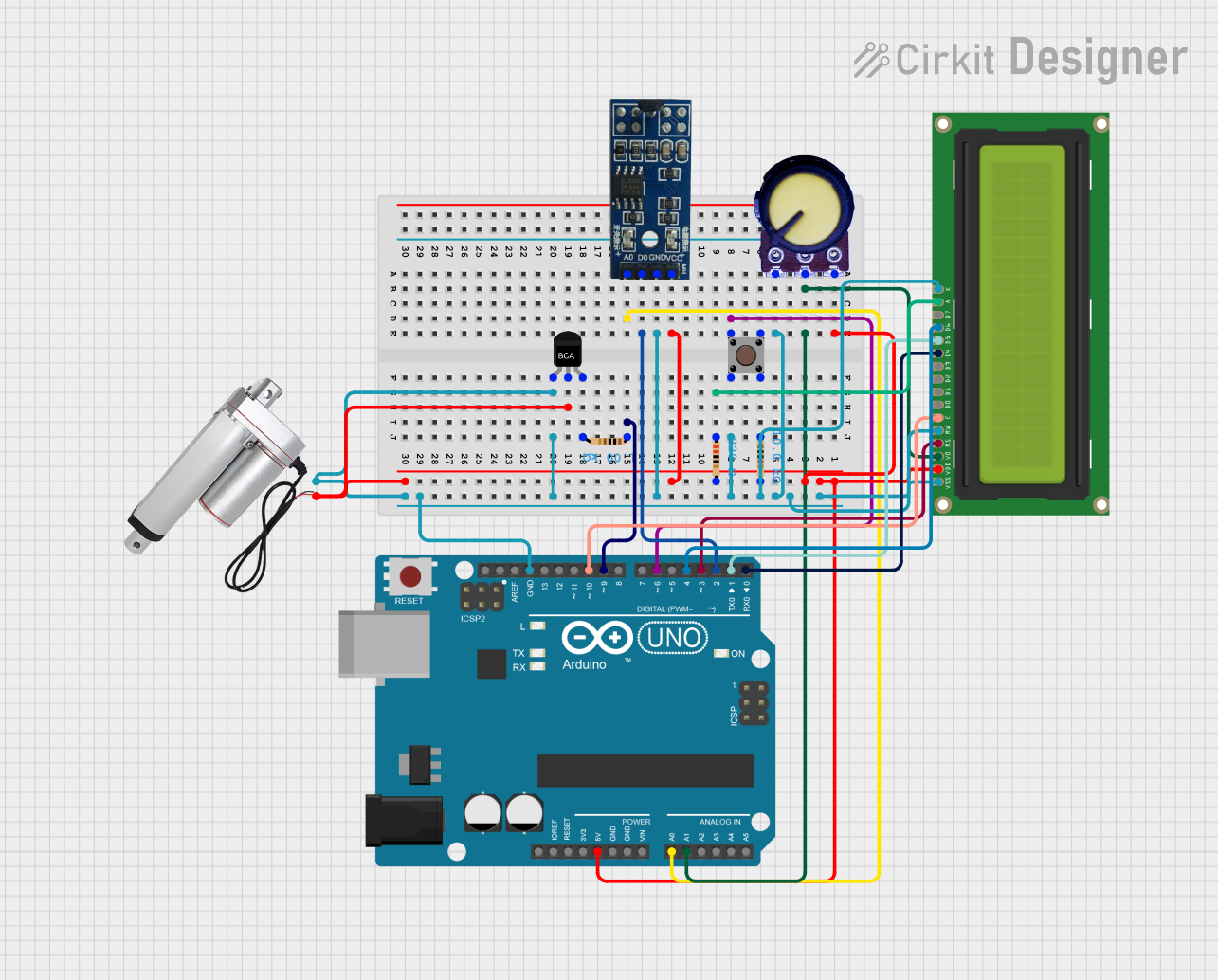
Circuit Diagram
- Connect the Vcc pin of the sensor to the 5V pin of the Arduino.
- Connect the GND pin of the sensor to the GND pin of the Arduino.
- Connect the OUT pin of the sensor to digital pin 2 of the Arduino.
Arduino Code
// Define the pin connected to the sensor's output
const int hallSensorPin = 2;
// Define an LED pin for visual feedback
const int ledPin = 13;

void setup() {
  pinMode(hallSensorPin, INPUT); // Set the sensor pin as input
  pinMode(ledPin, OUTPUT);       // Set the LED pin as output
  Serial.begin(9600);            // Initialize serial communication
}

void loop() {
  int sensorState = digitalRead(hallSensorPin); // Read the sensor's output

  if (sensorState == HIGH) {
    // Magnetic field detected
    digitalWrite(ledPin, HIGH); // Turn on the LED
    Serial.println("Magnetic field detected!");
  } else {
    // No magnetic field detected
    digitalWrite(ledPin, LOW);  // Turn off the LED
    Serial.println("No magnetic field.");
  }

  delay(100); // Small delay for stability
}
Troubleshooting and FAQs
Common Issues
No Output Signal:
- Ensure the power supply voltage is within the specified range (3.3V to 24V).
- Verify the connections, especially the GND and Vcc pins.
- Check if the magnet is positioned correctly and within the sensor's detection range.
Unstable Output:
- Add a decoupling capacitor (e.g., 0.1 µF) between Vcc and GND to filter noise.
- Ensure the pull-up resistor is correctly connected if using an open-drain output.
False Triggering:
- Avoid placing the sensor near strong electromagnetic interference (EMI) sources.
- Use shielding or ferrite beads if EMI is unavoidable.
FAQs
Q: Can the sensor detect both north and south poles of a magnet?
A: Yes, the TC-13492796 can detect both poles, but the output behavior may vary depending on the polarity.
Q: What type of magnets work best with this sensor?
A: Neodymium magnets are recommended due to their strong and consistent magnetic fields.
Q: Can I use this sensor for analog output?
A: No, the TC-13492796 provides a digital output only. For analog output, consider using a linear Hall effect sensor.
Q: Is the sensor waterproof?
A: The sensor itself is not waterproof. If used in wet environments, ensure proper encapsulation or housing.