How to Use INA226 Voltage and Current Monitoring Module: Examples, Pinouts, and Specs
Introduction
The INA226 is a high-side current shunt monitor with an integrated I2C interface, designed for precise voltage, current, and power measurements. Manufactured by Generic, this module is widely used in applications requiring accurate power monitoring, such as battery management systems, energy monitoring, and industrial automation.
Explore Projects Built with INA226 Voltage and Current Monitoring Module
Explore Projects Built with INA226 Voltage and Current Monitoring Module
Common Applications
- Battery management systems for electric vehicles and portable devices
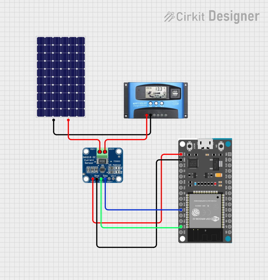
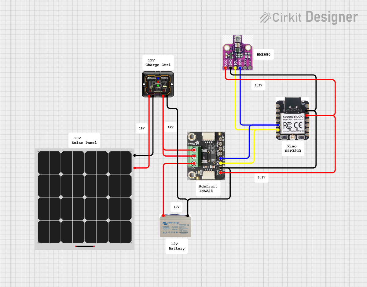
- Energy monitoring in renewable energy systems
- Industrial equipment power analysis
- IoT devices requiring real-time power consumption data
Technical Specifications
The INA226 module is designed to provide high accuracy and flexibility in power monitoring applications. Below are its key technical specifications:
Key Specifications
| Parameter | Value |
|---|---|
| Supply Voltage (Vcc) | 2.7V to 5.5V |
| Input Voltage Range | 0V to 36V |
| Current Measurement Range | Configurable (based on shunt) |
| Communication Interface | I2C (up to 400kHz) |
| Resolution | 16-bit |
| Operating Temperature | -40°C to +125°C |
| Power Consumption | 330 µA (typical) |
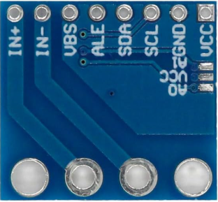
Pin Configuration
The INA226 module typically comes with a 6-pin interface. Below is the pinout description:
| Pin Name | Pin Number | Description |
|---|---|---|
| VCC | 1 | Power supply input (2.7V to 5.5V) |
| GND | 2 | Ground connection |
| SCL | 3 | I2C clock line |
| SDA | 4 | I2C data line |
| VIN+ | 5 | Positive input for voltage measurement |
| VIN- | 6 | Negative input for voltage measurement (shunt) |
Usage Instructions
The INA226 module is straightforward to use in a circuit. Below are the steps and best practices for integrating it into your project.
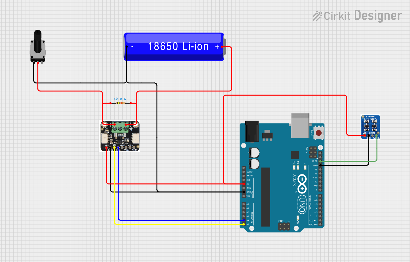
Connecting the INA226
- Power Supply: Connect the VCC pin to a 3.3V or 5V power source and the GND pin to the ground.
- Voltage Measurement: Connect the VIN+ and VIN- pins across the shunt resistor or the load whose current and voltage you want to measure.
- I2C Communication: Connect the SCL and SDA pins to the corresponding I2C pins on your microcontroller (e.g., Arduino UNO). Use pull-up resistors (typically 4.7kΩ) on the SCL and SDA lines if not already present.
Example Arduino Code
Below is an example of how to use the INA226 module with an Arduino UNO to measure voltage and current:
#include <Wire.h>

// INA226 I2C address (default is 0x40, but check your module's datasheet)
#define INA226_ADDRESS 0x40

void setup() {
  Wire.begin(); // Initialize I2C communication
  Serial.begin(9600); // Initialize serial communication for debugging

  // Configure INA226 (e.g., calibration settings)
  configureINA226();
}

void loop() {
  float busVoltage = readBusVoltage(); // Read bus voltage in volts
  float current = readCurrent();      // Read current in amperes

  // Print the measurements to the serial monitor
  Serial.print("Bus Voltage: ");
  Serial.print(busVoltage);
  Serial.println(" V");

  Serial.print("Current: ");
  Serial.print(current);
  Serial.println(" A");

  delay(1000); // Wait 1 second before the next reading
}

void configureINA226() {
  // Example configuration: Write calibration register
  Wire.beginTransmission(INA226_ADDRESS);
  Wire.write(0x05); // Calibration register address
  Wire.write(0x10); // High byte of calibration value
  Wire.write(0x00); // Low byte of calibration value
  Wire.endTransmission();
}

float readBusVoltage() {
  // Read bus voltage register (0x02)
  Wire.beginTransmission(INA226_ADDRESS);
  Wire.write(0x02); // Bus voltage register address
  Wire.endTransmission();

  Wire.requestFrom(INA226_ADDRESS, 2); // Request 2 bytes
  uint16_t rawData = (Wire.read() << 8) | Wire.read();

  // Convert raw data to voltage (1 LSB = 1.25 mV)
  return rawData * 0.00125;
}

float readCurrent() {
  // Read current register (0x04)
  Wire.beginTransmission(INA226_ADDRESS);
  Wire.write(0x04); // Current register address
  Wire.endTransmission();

  Wire.requestFrom(INA226_ADDRESS, 2); // Request 2 bytes
  uint16_t rawData = (Wire.read() << 8) | Wire.read();

  // Convert raw data to current (based on calibration settings)
  // Example assumes a calibration factor of 1 for simplicity
  return rawData * 0.001; // Adjust based on your calibration
}
Best Practices
- Use a precision shunt resistor with a known value for accurate current measurements.
- Ensure proper decoupling capacitors are placed near the VCC pin to reduce noise.
- Verify the I2C address of your INA226 module, as it may vary depending on the manufacturer.
Troubleshooting and FAQs
Common Issues
No I2C Communication:
- Ensure the SCL and SDA lines are connected correctly.
- Check for proper pull-up resistors on the I2C lines.
- Verify the I2C address of the module.
Incorrect Voltage or Current Readings:
- Double-check the shunt resistor value and connections.
- Ensure the calibration register is configured correctly.
Module Not Powering On:
- Verify the VCC and GND connections.
- Ensure the power supply voltage is within the specified range (2.7V to 5.5V).
FAQs
Q: Can the INA226 measure negative currents?
A: No, the INA226 is designed for high-side current measurement and cannot measure negative currents directly.
Q: What is the maximum current the INA226 can measure?
A: The maximum current depends on the value of the shunt resistor and the module's input voltage range. Ensure the shunt resistor is chosen to keep the voltage drop within the module's limits.
Q: Can I use the INA226 with a 3.3V microcontroller?
A: Yes, the INA226 supports a supply voltage range of 2.7V to 5.5V, making it compatible with both 3.3V and 5V systems.
By following this documentation, you can effectively integrate the INA226 module into your projects for precise voltage and current monitoring.