How to Use Bxxx-1W: Examples, Pinouts, and Specs
Introduction
The Bxxx-1W is a versatile electronic component commonly used in circuits for specialized functions such as signal processing and power management. Its unique model number signifies its specific design and capabilities, making it a reliable choice for engineers and hobbyists alike. The Bxxx-1W is known for its compact size, efficiency, and ease of integration into various electronic systems.
Explore Projects Built with Bxxx-1W


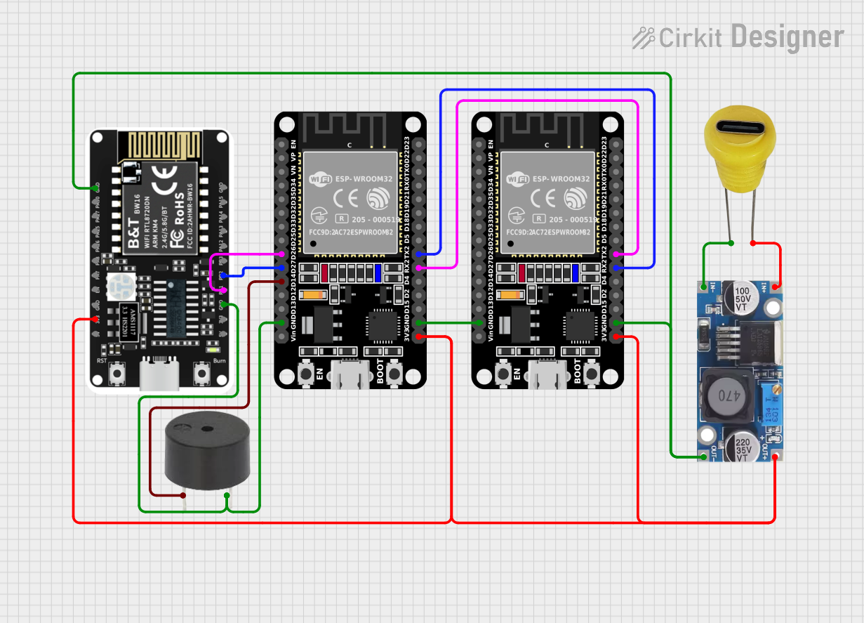
Explore Projects Built with Bxxx-1W
Common Applications and Use Cases
- Signal amplification and processing in communication systems
- Voltage regulation in power management circuits
- Integration into embedded systems for specialized tasks
- Use in prototyping and educational projects
Technical Specifications
The Bxxx-1W is designed to operate efficiently under a range of conditions. Below are its key technical details:
General Specifications
| Parameter | Value |
|---|---|
| Operating Voltage | 3.3V to 12V |
| Maximum Current | 1A |
| Power Rating | 1W |
| Operating Temperature | -40°C to +85°C |
| Package Type | Through-hole or SMD |
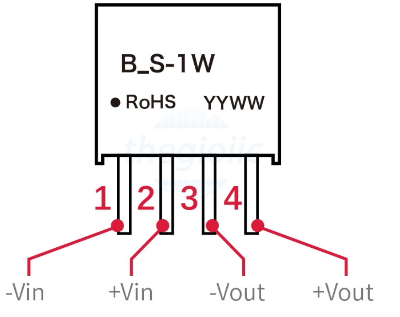
Pin Configuration and Descriptions
The Bxxx-1W typically comes with a 3-pin configuration. The table below describes each pin:
| Pin Number | Pin Name | Description |
|---|---|---|
| 1 | Input (+) | Positive input voltage terminal |
| 2 | Ground (G) | Ground connection for the circuit |
| 3 | Output (+) | Positive output voltage terminal |
Usage Instructions
To use the Bxxx-1W in a circuit, follow these steps:
- Determine the Input Voltage: Ensure the input voltage is within the specified range (3.3V to 12V). Exceeding this range may damage the component.
- Connect the Pins:
- Connect the input voltage source to the
Input (+)pin. - Connect the
Ground (G)pin to the circuit's ground. - Connect the
Output (+)pin to the load or circuit requiring the regulated output.
- Connect the input voltage source to the
- Verify Connections: Double-check all connections to avoid short circuits or incorrect wiring.
- Power On the Circuit: Once all connections are secure, power on the circuit and measure the output to ensure proper operation.
Important Considerations and Best Practices
- Heat Dissipation: If the component operates near its maximum power rating (1W), ensure adequate heat dissipation using a heatsink or proper ventilation.
- Polarity: Always observe correct polarity when connecting the input and output terminals.
- Load Requirements: Ensure the connected load does not exceed the maximum current rating of 1A.
Example: Using Bxxx-1W with an Arduino UNO
The Bxxx-1W can be used to regulate power for an Arduino UNO or other microcontrollers. Below is an example of how to connect it:
// Example: Using Bxxx-1W to power an Arduino UNO
// Ensure the input voltage to the Bxxx-1W is within 3.3V to 12V.
// The output of the Bxxx-1W will power the Arduino UNO.

void setup() {
  // No specific code is required for the Bxxx-1W itself,
  // as it is a hardware component. Ensure proper wiring:
  // - Input (+) to a 9V battery or power source
  // - Ground (G) to the Arduino GND pin
  // - Output (+) to the Arduino VIN pin
}

void loop() {
  // Your Arduino code goes here
  // Example: Blink an LED connected to pin 13
  pinMode(13, OUTPUT);
  digitalWrite(13, HIGH); // Turn LED on
  delay(1000);            // Wait 1 second
  digitalWrite(13, LOW);  // Turn LED off
  delay(1000);            // Wait 1 second
}
Troubleshooting and FAQs
Common Issues and Solutions
No Output Voltage:
- Cause: Incorrect wiring or insufficient input voltage.
- Solution: Verify the input voltage is within the specified range and check all connections.
Overheating:
- Cause: Excessive load or poor heat dissipation.
- Solution: Reduce the load or add a heatsink to the component.
Output Voltage Fluctuations:
- Cause: Unstable input voltage or interference.
- Solution: Use a capacitor across the input and ground pins to stabilize the input voltage.
FAQs
Q: Can the Bxxx-1W handle AC input?
A: No, the Bxxx-1W is designed for DC input only. Applying AC voltage may damage the component.
Q: What is the maximum load I can connect to the output?
A: The maximum load should not exceed 1A, as specified in the technical specifications.
Q: Can I use the Bxxx-1W in high-temperature environments?
A: Yes, the Bxxx-1W can operate in temperatures up to +85°C. However, ensure proper heat dissipation to avoid performance issues.
By following this documentation, you can effectively integrate the Bxxx-1W into your projects and troubleshoot any issues that arise.