How to Use Stepdown XL4016: Examples, Pinouts, and Specs
Introduction
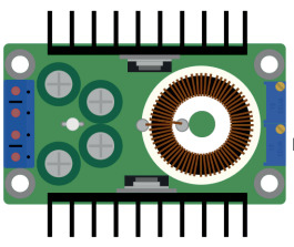
The Stepdown XL4016 is a DC-DC buck converter module manufactured by XLSEMI. It is designed to efficiently step down voltage from a higher input level to a lower output level. With its ability to handle input voltages up to 36V and output currents up to 5A, the XL4016 is a versatile and reliable component for a wide range of applications.
Explore Projects Built with Stepdown XL4016


Explore Projects Built with Stepdown XL4016
Common Applications and Use Cases
- Powering low-voltage devices from higher-voltage power sources (e.g., batteries, solar panels)
- Voltage regulation in embedded systems
- DIY electronics projects requiring adjustable voltage outputs
- Powering LED strips, motors, or other DC loads
- Battery charging circuits
Technical Specifications
The XL4016 module is built for high efficiency and robust performance. Below are its key technical details:
Key Specifications
| Parameter | Value |
|---|---|
| Input Voltage Range | 8V to 36V |
| Output Voltage Range | 1.25V to 32V (adjustable) |
| Maximum Output Current | 5A (with proper heat dissipation) |
| Efficiency | Up to 96% |
| Switching Frequency | 180 kHz |
| Operating Temperature | -40°C to +85°C |
| Dimensions | Approx. 60mm x 53mm x 22mm |
Pin Configuration and Descriptions
| Pin Name | Description |
|---|---|
| VIN+ | Positive input voltage terminal (connect to the higher voltage source) |
| VIN- | Negative input voltage terminal (connect to the ground of the power source) |
| VOUT+ | Positive output voltage terminal (connect to the load) |
| VOUT- | Negative output voltage terminal (connect to the ground of the load) |
| Potentiometer | Adjustable knob to set the output voltage |
Usage Instructions
How to Use the XL4016 in a Circuit
Connect the Input Voltage:
- Connect the positive terminal of your power source to the
VIN+pin. - Connect the ground terminal of your power source to the
VIN-pin. - Ensure the input voltage is within the range of 8V to 36V.
- Connect the positive terminal of your power source to the
Connect the Output Load:
- Connect the positive terminal of your load to the
VOUT+pin. - Connect the ground terminal of your load to the
VOUT-pin.
- Connect the positive terminal of your load to the
Adjust the Output Voltage:
- Use the onboard potentiometer to adjust the output voltage.
- Turn the potentiometer clockwise to increase the voltage and counterclockwise to decrease it.
- Use a multimeter to measure the output voltage for precise adjustment.
Heat Dissipation:
- If the output current exceeds 3A, ensure proper heat dissipation by attaching a heatsink or using active cooling (e.g., a fan).
Power On:
- Once all connections are secure, power on the module and verify the output voltage and current.
Important Considerations and Best Practices
- Input Voltage: Ensure the input voltage is at least 1.5V higher than the desired output voltage for proper regulation.
- Current Limitation: Do not exceed the maximum output current of 5A to avoid damaging the module.
- Heat Management: For high-power applications, monitor the module's temperature and use additional cooling if necessary.
- Polarity: Double-check the polarity of all connections to prevent damage to the module or connected devices.
Example: Using XL4016 with Arduino UNO
The XL4016 can be used to power an Arduino UNO by stepping down a higher voltage (e.g., 12V) to 5V. Below is an example circuit and code:
Circuit Setup
- Connect a 12V power source to the
VIN+andVIN-pins of the XL4016. - Adjust the potentiometer to set the output voltage to 5V.
- Connect the
VOUT+pin to the Arduino's 5V pin. - Connect the
VOUT-pin to the Arduino's GND pin.
Arduino Code Example
// Example code to blink an LED using Arduino UNO powered by XL4016
// Ensure the XL4016 output is set to 5V before connecting to the Arduino

const int ledPin = 13; // Pin connected to the onboard LED

void setup() {
  pinMode(ledPin, OUTPUT); // Set the LED pin as an output
}

void loop() {
  digitalWrite(ledPin, HIGH); // Turn the LED on
  delay(1000);               // Wait for 1 second
  digitalWrite(ledPin, LOW);  // Turn the LED off
  delay(1000);               // Wait for 1 second
}
Troubleshooting and FAQs
Common Issues and Solutions
| Issue | Possible Cause | Solution |
|---|---|---|
| No output voltage | Incorrect wiring or loose connections | Verify all connections and polarity |
| Output voltage not adjustable | Faulty potentiometer or incorrect setup | Check the potentiometer and input voltage |
| Module overheating | Excessive current draw or poor cooling | Reduce load current or add a heatsink |
| Output voltage fluctuates | Insufficient input voltage or noise | Ensure stable input voltage and add capacitors for filtering |
FAQs
Can the XL4016 be used for battery charging?
- Yes, but ensure the output voltage and current are set according to the battery's specifications.
What happens if the input voltage exceeds 36V?
- The module may be damaged. Always ensure the input voltage stays within the specified range.
Can I use the XL4016 to power sensitive electronics?
- Yes, but consider adding additional filtering capacitors to reduce noise for sensitive devices.
How do I calculate the power dissipation?
- Power dissipation can be estimated as ( P = (V_{in} - V_{out}) \times I_{out} ). Ensure proper cooling for high dissipation values.
By following this documentation, you can effectively use the XL4016 in your projects while ensuring safety and optimal performance.