How to Use Load Cell 20Kg: Examples, Pinouts, and Specs

Introduction
A Load Cell 20Kg is a type of transducer that converts a force or weight into an electrical signal. It is designed to measure loads up to 20 kilograms with high accuracy and reliability. The load cell operates by deforming slightly under the applied weight, and this deformation is detected by strain gauges, which produce a proportional electrical signal.
Explore Projects Built with Load Cell 20Kg
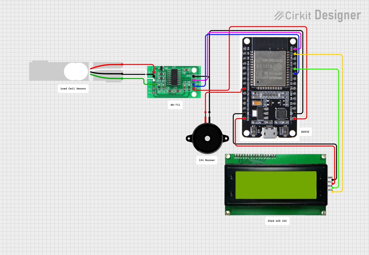
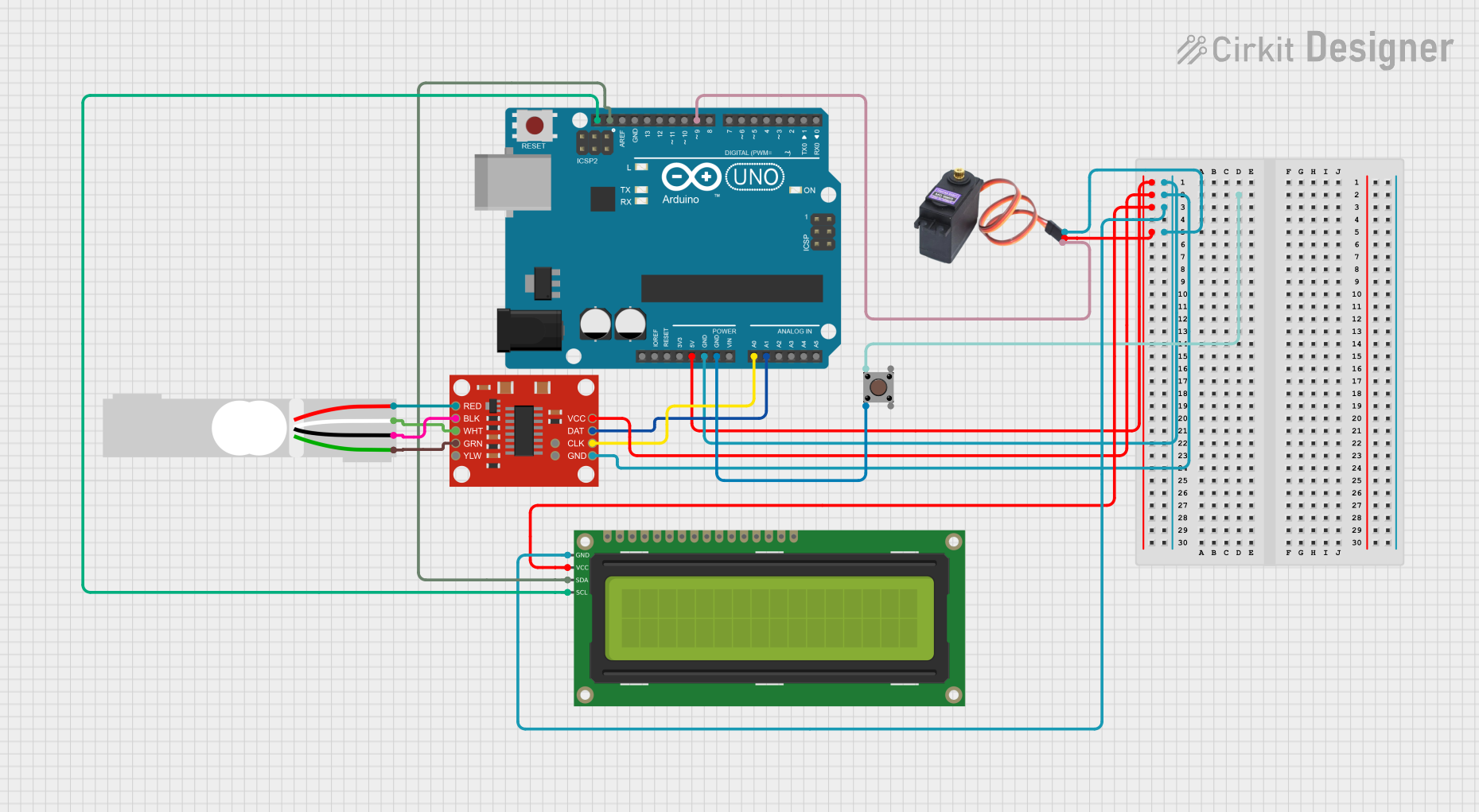
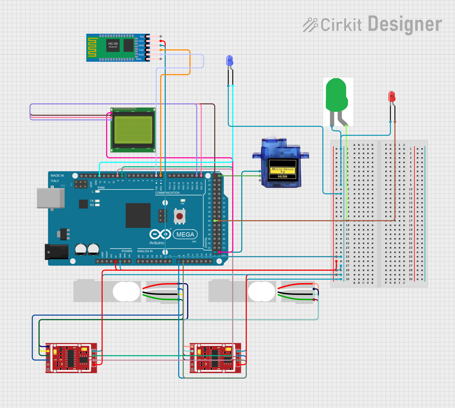
Explore Projects Built with Load Cell 20Kg
Common Applications and Use Cases
- Digital weighing scales
- Industrial automation systems
- Force measurement in robotics
- Material testing machines
- IoT-based weight monitoring systems
Technical Specifications
Below are the key technical details of the Load Cell 20Kg:
| Parameter | Specification |
|---|---|
| Rated Load | 20 kg |
| Output Sensitivity | 1.0 ± 0.1 mV/V |
| Input Resistance | 1,000 ± 10 Ω |
| Output Resistance | 1,000 ± 10 Ω |
| Excitation Voltage | 5V to 12V DC (recommended 10V) |
| Maximum Excitation | 15V DC |
| Safe Overload Limit | 150% of rated load |
| Operating Temperature | -10°C to +40°C |
| Material | Aluminum alloy |
| Accuracy Class | C2 (±0.02% FS) |
Pin Configuration and Descriptions
The Load Cell 20Kg typically has four wires for electrical connections. The pinout is as follows:
| Wire Color | Function | Description |
|---|---|---|
| Red | Excitation+ (E+) | Positive power supply for the strain gauge bridge. |
| Black | Excitation- (E-) | Negative power supply for the strain gauge bridge. |
| White | Signal+ (S+) | Positive output signal from the strain gauge. |
| Green | Signal- (S-) | Negative output signal from the strain gauge. |
Usage Instructions
How to Use the Load Cell in a Circuit
Wiring the Load Cell:
- Connect the red wire (E+) to the positive terminal of the excitation voltage (e.g., 5V or 10V DC).
- Connect the black wire (E-) to the ground (GND) of the power supply.
- Connect the white wire (S+) to the positive input of an amplifier or ADC (Analog-to-Digital Converter).
- Connect the green wire (S-) to the negative input of the amplifier or ADC.
Amplification and Signal Processing:
- The output signal of the load cell is in millivolts (mV) and needs to be amplified using a load cell amplifier, such as the HX711 module.
- The amplified signal can then be read by a microcontroller (e.g., Arduino) for further processing.
Calibration:
- Perform a calibration process to map the raw ADC values to actual weight values. This involves applying known weights and recording the corresponding readings.
Important Considerations and Best Practices
- Avoid Overloading: Do not exceed the safe overload limit (150% of the rated load) to prevent permanent damage.
- Stable Mounting: Ensure the load cell is securely mounted to avoid measurement errors due to vibrations or misalignment.
- Temperature Effects: Use the load cell within the specified operating temperature range to maintain accuracy.
- Shielding: Use shielded cables to minimize noise interference in the signal.
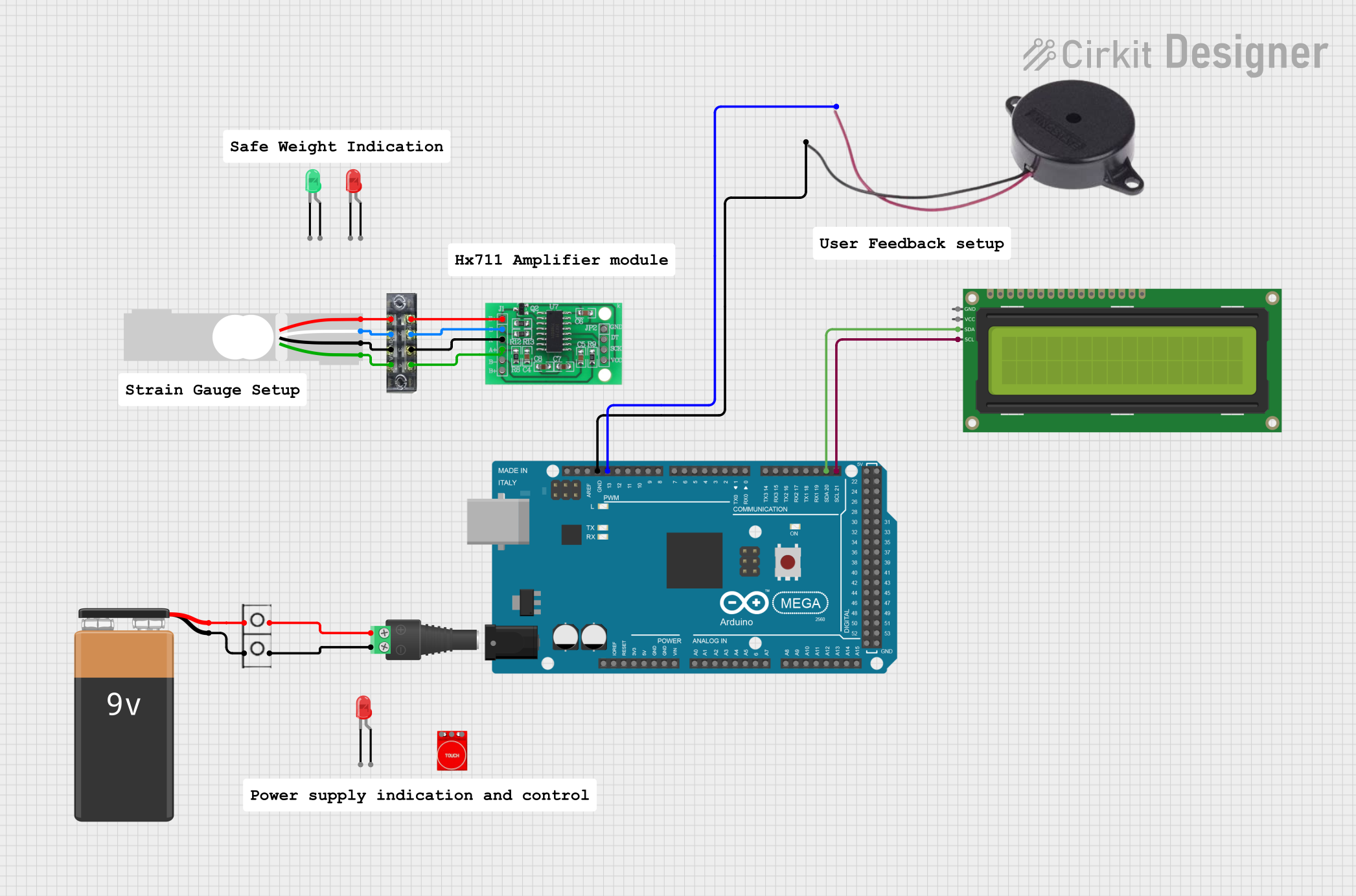
Example: Using Load Cell 20Kg with Arduino UNO
Below is an example of how to connect and use the Load Cell 20Kg with an Arduino UNO and an HX711 amplifier module:
Circuit Diagram
- Connect the load cell wires to the HX711 module as follows:
- Red (E+) → E+ on HX711
- Black (E-) → E- on HX711
- White (S+) → A+ on HX711
- Green (S-) → A- on HX711
- Connect the HX711 module to the Arduino UNO:
- VCC → 5V
- GND → GND
- DT → Digital Pin 3
- SCK → Digital Pin 2
Arduino Code
#include "HX711.h" // Include HX711 library for load cell

// Define pins for HX711 module
#define DT 3  // Data pin connected to digital pin 3
#define SCK 2 // Clock pin connected to digital pin 2

HX711 scale; // Create an instance of the HX711 class

void setup() {
  Serial.begin(9600); // Initialize serial communication
  scale.begin(DT, SCK); // Initialize HX711 with defined pins

  Serial.println("Calibrating... Place a known weight on the load cell.");
  delay(5000); // Wait for user to place a weight
  scale.set_scale(); // Set the scale to default calibration factor
  scale.tare(); // Reset the scale to zero
  Serial.println("Calibration complete.");
}

void loop() {
  // Read weight from the load cell
  float weight = scale.get_units(10); // Average of 10 readings
  Serial.print("Weight: ");
  Serial.print(weight);
  Serial.println(" kg");

  delay(1000); // Wait 1 second before the next reading
}
Note: Replace the default calibration factor in the
scale.set_scale()function with the appropriate value for your setup after calibration.
Troubleshooting and FAQs
Common Issues and Solutions
No Output Signal:
- Cause: Incorrect wiring or loose connections.
- Solution: Double-check all connections and ensure the wires are securely connected.
Inconsistent Readings:
- Cause: Vibrations, unstable mounting, or electrical noise.
- Solution: Mount the load cell securely and use shielded cables to reduce noise.
Incorrect Weight Measurements:
- Cause: Calibration not performed or incorrect calibration factor.
- Solution: Perform the calibration process with known weights and update the calibration factor.
Signal Saturation:
- Cause: Exceeding the rated load of the load cell.
- Solution: Ensure the applied load does not exceed 20 kg.
FAQs
Q1: Can I use the Load Cell 20Kg with a 3.3V microcontroller?
A1: Yes, but ensure the excitation voltage is within the load cell's operating range (5V to 12V). Use a level shifter if necessary for signal compatibility.
Q2: How do I protect the load cell from environmental factors?
A2: Use a protective enclosure or coating to shield the load cell from moisture, dust, and extreme temperatures.
Q3: Can I use multiple load cells in a single system?
A3: Yes, you can connect multiple load cells in a parallel configuration to measure larger weights or distribute the load evenly.
Q4: What is the lifespan of a Load Cell 20Kg?
A4: With proper usage and within the specified limits, the load cell can last for several years.