
How to Use VL53L1X: Examples, Pinouts, and Specs
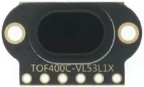
 Design with VL53L1X in Cirkit Designer
Introduction
The VL53L1X is a state-of-the-art time-of-flight (ToF) distance sensor manufactured by STMicroelectronics. It utilizes laser technology to measure distances with high precision, offering a range of up to 4 meters. This compact sensor is designed for low power consumption and can operate reliably in various lighting conditions, including complete darkness. Its versatility makes it an excellent choice for applications in robotics, drones, automation, gesture recognition, and proximity sensing.
Explore Projects Built with VL53L1X
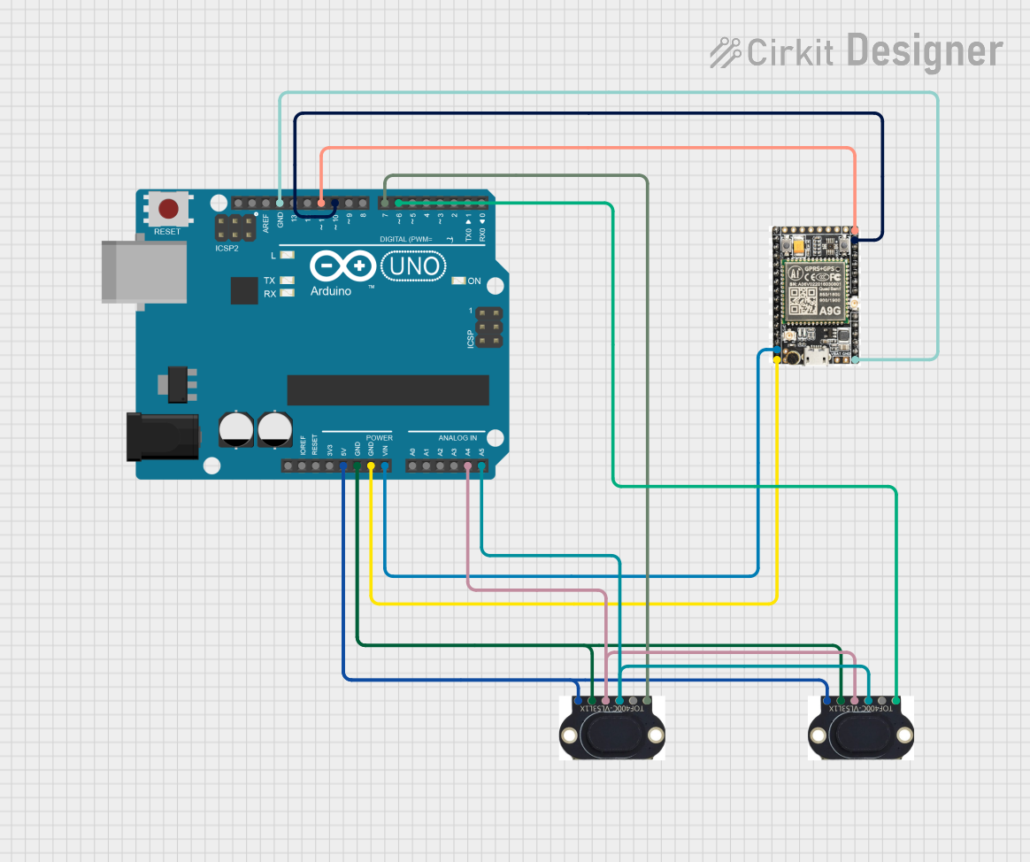 Open Project in Cirkit Designer
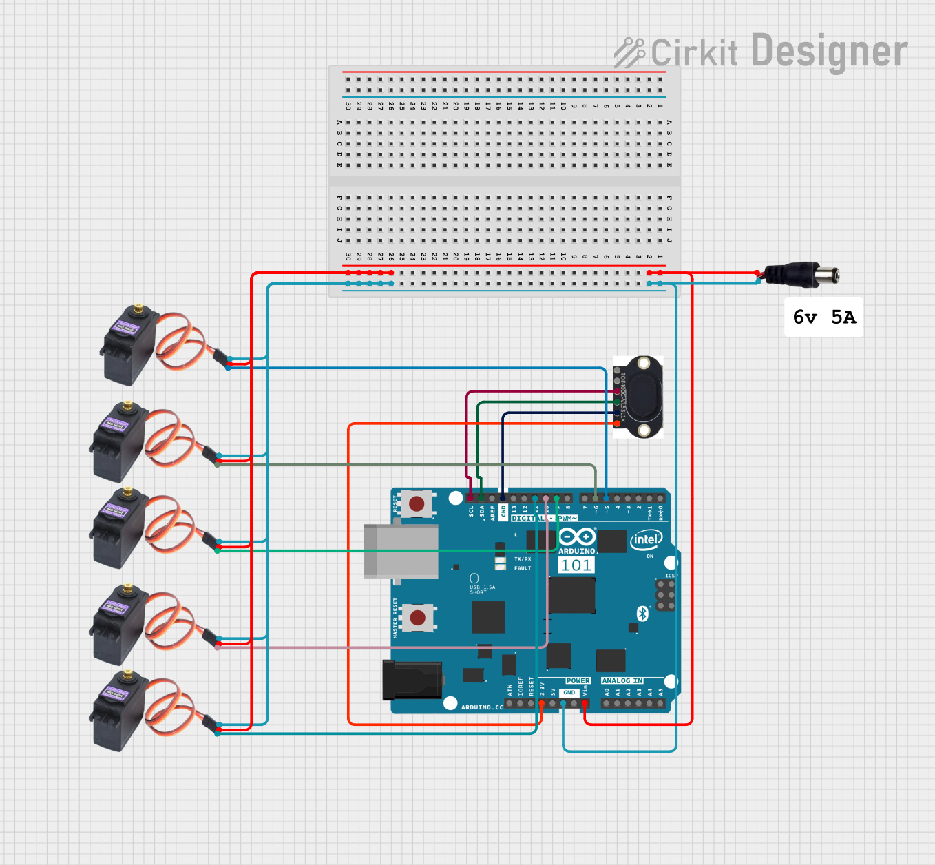 Open Project in Cirkit Designer
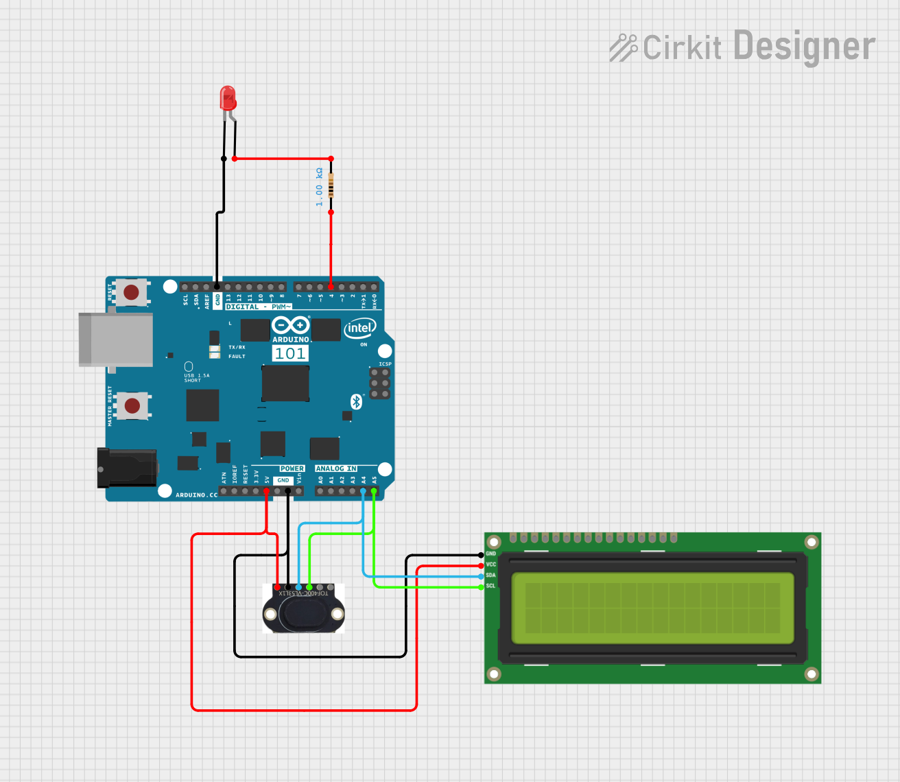 Open Project in Cirkit Designer
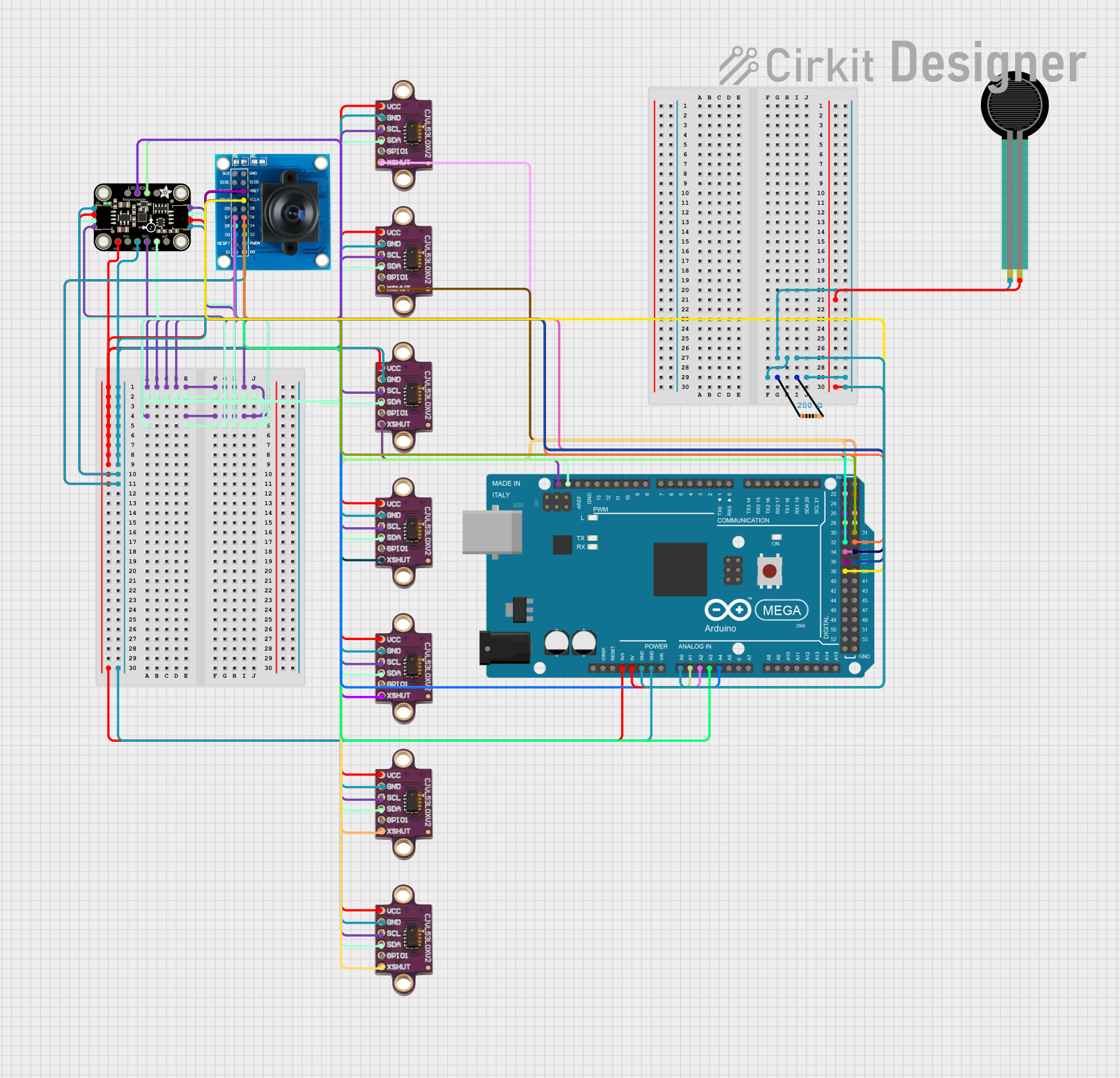 Open Project in Cirkit Designer
Explore Projects Built with VL53L1X
Open Project in Cirkit DesignerOpen Project in Cirkit DesignerOpen Project in Cirkit DesignerOpen Project in Cirkit DesignerCommon Applications:
- Obstacle detection in robotics and drones
- Proximity sensing in smart devices
- Gesture recognition for user interfaces
- Distance measurement in industrial automation
- Presence detection in security systems
Technical Specifications
The VL53L1X is a highly capable sensor with the following key specifications:
| Parameter | Value |
|---|---|
| Operating Voltage | 2.6V to 3.5V |
| Communication Interface | I²C |
| Measurement Range | 4 cm to 400 cm (0.04 m to 4 m) |
| Accuracy | ±1 mm (typical) |
| Field of View (FoV) | Programmable, up to 27° |
| Power Consumption | 20 mW (typical) |
| Operating Temperature Range | -20°C to +85°C |
| Dimensions | 4.9 mm x 2.5 mm x 1.56 mm |
Pin Configuration and Descriptions
The VL53L1X sensor module typically comes with the following pinout:
| Pin Name | Description |
|---|---|
| VIN | Power supply input (2.6V to 3.5V) |
| GND | Ground |
| SDA | I²C data line for communication |
| SCL | I²C clock line for communication |
| XSHUT | Shutdown pin (active low, used to reset the sensor) |
| GPIO1 | Interrupt output (optional, configurable) |
Usage Instructions
How to Use the VL53L1X in a Circuit
- Power Supply: Connect the VIN pin to a 3.3V power source and the GND pin to ground.
- I²C Communication: Connect the SDA and SCL pins to the corresponding I²C pins on your microcontroller (e.g., Arduino or ESP32). Use pull-up resistors (typically 4.7 kΩ) on the SDA and SCL lines if not already included on the breakout board.
- Shutdown Pin: Optionally, connect the XSHUT pin to a GPIO pin on your microcontroller to enable or disable the sensor programmatically.
- Interrupt Pin: If needed, connect the GPIO1 pin to a GPIO pin on your microcontroller to handle interrupts.
Important Considerations:
- Ensure the sensor is not exposed to direct sunlight or reflective surfaces that may interfere with measurements.
- Avoid placing the sensor too close to objects (<4 cm), as it may not provide accurate readings.
- Use a stable power supply to minimize noise and ensure reliable operation.
Example Code for Arduino UNO
Below is an example of how to interface the VL53L1X with an Arduino UNO using the Adafruit VL53L1X library:
#include <Wire.h>
#include <Adafruit_VL53L1X.h>

// Create an instance of the VL53L1X sensor
Adafruit_VL53L1X vl53 = Adafruit_VL53L1X();

void setup() {
  Serial.begin(115200); // Initialize serial communication
  while (!Serial) delay(10); // Wait for Serial Monitor to open

  Serial.println("VL53L1X Test");

  // Initialize the sensor
  if (!vl53.begin()) {
    Serial.println("Failed to find VL53L1X sensor!");
    while (1); // Halt execution if sensor initialization fails
  }

  Serial.println("VL53L1X sensor initialized successfully.");
  vl53.startRanging(); // Start ranging mode
}

void loop() {
  // Read distance in millimeters
  uint16_t distance = vl53.read();

  // Check if the reading is valid
  if (distance != 0) {
    Serial.print("Distance: ");
    Serial.print(distance);
    Serial.println(" mm");
  } else {
    Serial.println("Error: Unable to read distance.");
  }

  delay(100); // Wait 100 ms before the next reading
}
Notes:
- Install the Adafruit VL53L1X library via the Arduino Library Manager before running the code.
- Ensure the I²C address of the sensor matches the default address (0x29) or modify the code accordingly.
Troubleshooting and FAQs
Common Issues and Solutions
Sensor Not Detected:
- Ensure the sensor is powered correctly (VIN and GND connected).
- Verify the I²C connections (SDA and SCL) and check for loose wires.
- Confirm the I²C address matches the default (0x29) or update the code.
Inaccurate Distance Measurements:
- Avoid reflective or transparent surfaces in the sensor's field of view.
- Ensure the sensor is not too close to the object (<4 cm).
- Check for interference from ambient light or other nearby sensors.
Intermittent Readings:
- Use pull-up resistors on the SDA and SCL lines if not already present.
- Verify the power supply is stable and noise-free.
FAQs
Q: Can the VL53L1X measure distances beyond 4 meters?
A: No, the maximum range of the VL53L1X is 4 meters. For longer distances, consider other sensors like the VL53L4CX.
Q: Can I use multiple VL53L1X sensors on the same I²C bus?
A: Yes, but you must change the I²C address of each sensor using the XSHUT pin to avoid address conflicts.
Q: Is the VL53L1X affected by ambient light?
A: The sensor is designed to work in various lighting conditions, but extreme ambient light (e.g., direct sunlight) may reduce accuracy.
Q: Can the VL53L1X detect transparent objects?
A: No, the sensor may struggle to detect transparent or highly reflective objects accurately.
By following this documentation, users can effectively integrate the VL53L1X into their projects and troubleshoot common issues with ease.