How to Use ESP32 WROOM-32 C Type CP2102 USB Dual Core WiFi + Bluetooth 38 Pins: Examples, Pinouts, and Specs
Introduction
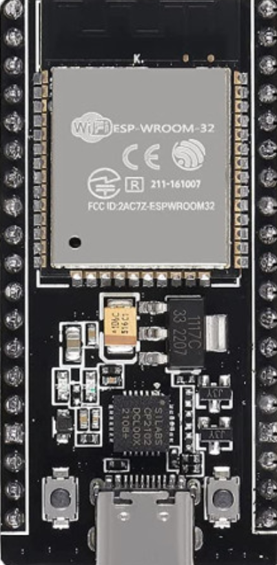
The ESP32 WROOM-32 C Type CP2102 USB is a versatile and powerful microcontroller module manufactured by ESP32. It features a dual-core processor, integrated WiFi and Bluetooth capabilities, and 38 GPIO pins, making it ideal for a wide range of IoT, automation, and embedded system applications. The inclusion of the CP2102 USB interface simplifies programming and connectivity, allowing seamless integration with development environments.
Explore Projects Built with ESP32 WROOM-32 C Type CP2102 USB Dual Core WiFi + Bluetooth 38 Pins


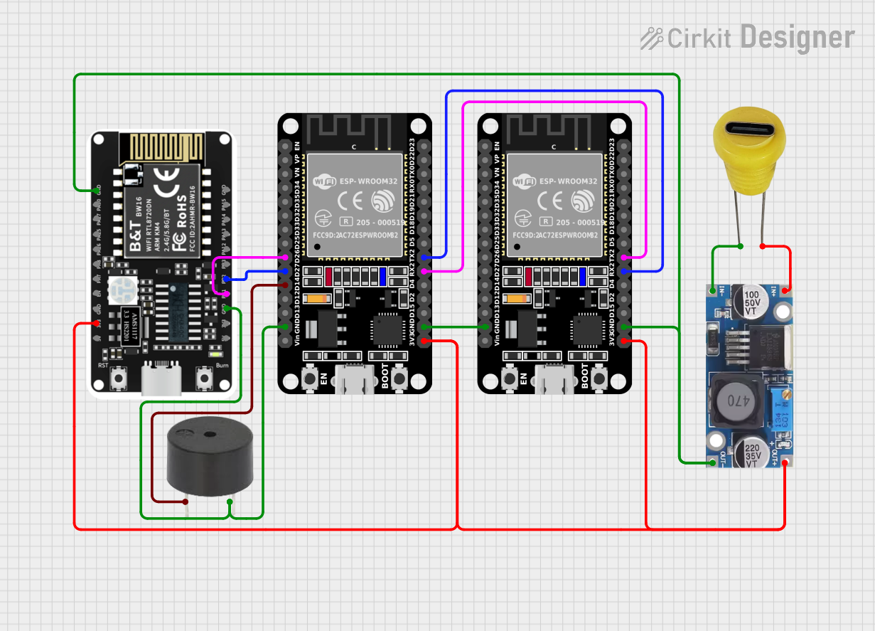
Explore Projects Built with ESP32 WROOM-32 C Type CP2102 USB Dual Core WiFi + Bluetooth 38 Pins
Common Applications and Use Cases
- IoT devices and smart home automation
- Wireless sensor networks
- Wearable technology
- Robotics and drones
- Industrial automation
- Prototyping and educational projects
Technical Specifications
Below are the key technical details of the ESP32 WROOM-32 C Type module:
| Specification | Details |
|---|---|
| Manufacturer | ESP32 |
| Part ID | ESP32-Wroom-38-C-Type |
| Processor | Dual-core Xtensa® 32-bit LX6 microprocessor |
| Clock Speed | Up to 240 MHz |
| Flash Memory | 4 MB |
| SRAM | 520 KB |
| Wireless Connectivity | WiFi 802.11 b/g/n, Bluetooth v4.2 + BLE |
| USB Interface | CP2102 USB-to-UART bridge |
| GPIO Pins | 38 pins |
| Operating Voltage | 3.3V |
| Input Voltage Range | 5V (via USB) or 3.3V (via VIN pin) |
| Power Consumption | Ultra-low power consumption in deep sleep mode (as low as 10 µA) |
| Operating Temperature | -40°C to +85°C |
| Dimensions | 25.5 mm x 18 mm |
Pin Configuration and Descriptions
The ESP32 WROOM-32 C Type module has 38 pins, each with specific functions. Below is a summary of the pin configuration:
| Pin Number | Pin Name | Function |
|---|---|---|
| 1 | EN | Enable pin (active high) |
| 2 | IO0 | GPIO0, used for boot mode selection |
| 3 | IO1 (TX0) | GPIO1, UART0 TX |
| 4 | IO3 (RX0) | GPIO3, UART0 RX |
| 5 | IO4 | GPIO4, general-purpose I/O |
| 6 | IO5 | GPIO5, general-purpose I/O |
| 7 | IO12 | GPIO12, general-purpose I/O |
| 8 | IO13 | GPIO13, general-purpose I/O |
| 9 | IO14 | GPIO14, general-purpose I/O |
| 10 | IO15 | GPIO15, general-purpose I/O |
| 11 | IO16 | GPIO16, general-purpose I/O |
| 12 | IO17 | GPIO17, general-purpose I/O |
| 13 | IO18 | GPIO18, SPI clock (SCK) |
| 14 | IO19 | GPIO19, SPI MISO |
| 15 | IO21 | GPIO21, I2C SDA |
| 16 | IO22 | GPIO22, I2C SCL |
| 17 | IO23 | GPIO23, SPI MOSI |
| 18 | GND | Ground |
| 19 | 3V3 | 3.3V power output |
| 20 | VIN | Input voltage (3.3V or 5V) |
Note: For a complete pinout diagram, refer to the official ESP32 datasheet.
Usage Instructions
How to Use the ESP32 WROOM-32 C Type in a Circuit
Powering the Module:
- Connect the module to a 5V power source via the USB port or supply 3.3V to the VIN pin.
- Ensure the power supply is stable to avoid damage to the module.
Programming the Module:
- Install the CP2102 USB driver on your computer (available on the manufacturer's website).
- Use the Arduino IDE or ESP-IDF (Espressif IoT Development Framework) for programming.
- Select the correct board type (
ESP32 Dev Module) and COM port in the IDE.
Connecting Peripherals:
- Use the GPIO pins to connect sensors, actuators, or other peripherals.
- For I2C devices, use GPIO21 (SDA) and GPIO22 (SCL).
- For SPI devices, use GPIO18 (SCK), GPIO19 (MISO), and GPIO23 (MOSI).
Uploading Code:
- Press and hold the
BOOTbutton while uploading code to enter programming mode. - Release the button once the upload begins.
- Press and hold the
Important Considerations and Best Practices
- Use a level shifter if interfacing with 5V logic devices, as the ESP32 operates at 3.3V logic levels.
- Avoid connecting high-current devices directly to GPIO pins; use transistors or relays instead.
- Use decoupling capacitors near the power pins to ensure stable operation.
Example Code for Arduino IDE
Below is an example code to connect the ESP32 to a WiFi network and print the IP address:
#include <WiFi.h> // Include the WiFi library

const char* ssid = "Your_SSID";       // Replace with your WiFi network name
const char* password = "Your_Password"; // Replace with your WiFi password

void setup() {
  Serial.begin(115200); // Initialize serial communication at 115200 baud
  delay(1000);          // Wait for a moment

  Serial.println("Connecting to WiFi...");
  WiFi.begin(ssid, password); // Start WiFi connection

  while (WiFi.status() != WL_CONNECTED) {
    delay(500); // Wait until connected
    Serial.print(".");
  }

  Serial.println("\nWiFi connected!");
  Serial.print("IP Address: ");
  Serial.println(WiFi.localIP()); // Print the assigned IP address
}

void loop() {
  // Add your main code here
}
Tip: Replace
Your_SSIDandYour_Passwordwith your WiFi credentials.
Troubleshooting and FAQs
Common Issues and Solutions
Problem: The ESP32 is not detected by the computer.
Solution:- Ensure the CP2102 USB driver is installed correctly.
- Try a different USB cable or port.
Problem: Code upload fails with a timeout error.
Solution:- Press and hold the
BOOTbutton while uploading the code. - Check the selected COM port and board type in the Arduino IDE.
- Press and hold the
Problem: WiFi connection fails.
Solution:- Verify the SSID and password.
- Ensure the WiFi network is within range.
FAQs
Q: Can the ESP32 operate on battery power?
A: Yes, the ESP32 can be powered by a 3.7V LiPo battery connected to the VIN pin.Q: How do I reset the ESP32?
A: Press theENbutton to reset the module.Q: Can I use the ESP32 with 5V logic devices?
A: No, the ESP32 operates at 3.3V logic levels. Use a level shifter for compatibility.
This concludes the documentation for the ESP32 WROOM-32 C Type CP2102 USB Dual Core WiFi + Bluetooth 38 Pins module. For further details, refer to the official datasheet or user manual.