
How to Use PIC18F2455: Examples, Pinouts, and Specs
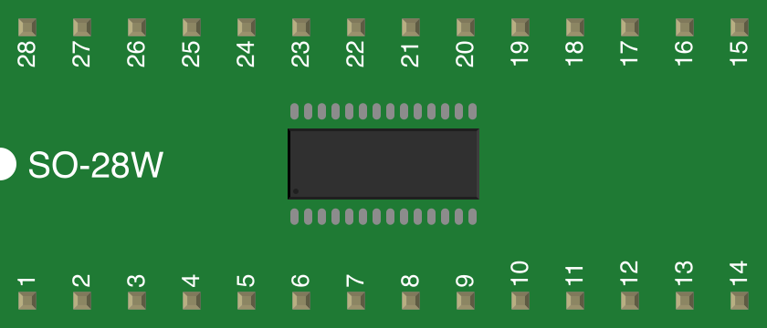
 Design with PIC18F2455 in Cirkit Designer
Introduction
The PIC18F2455 is an 8-bit microcontroller developed by Microchip Technology. It features a 14-bit instruction set architecture, 32 KB of Flash memory, 2 KB of RAM, and a variety of integrated peripherals. These include an Analog-to-Digital Converter (ADC), timers, and communication interfaces such as UART, SPI, and I2C. Its versatility and robust feature set make it ideal for a wide range of embedded applications, including industrial automation, consumer electronics, and data acquisition systems.
Explore Projects Built with PIC18F2455
 Open Project in Cirkit Designer
 Open Project in Cirkit Designer
 Open Project in Cirkit Designer
 Open Project in Cirkit Designer
Explore Projects Built with PIC18F2455
Open Project in Cirkit DesignerOpen Project in Cirkit DesignerOpen Project in Cirkit DesignerOpen Project in Cirkit DesignerCommon Applications
- USB-enabled embedded systems
- Data logging and acquisition
- Industrial control systems
- Home automation
- Prototyping and educational projects
Technical Specifications
Key Technical Details
| Parameter | Value |
|---|---|
| CPU Architecture | 8-bit |
| Instruction Set | 14-bit |
| Flash Memory | 32 KB |
| RAM | 2 KB |
| EEPROM | 256 Bytes |
| Operating Voltage Range | 2.0V to 5.5V |
| Clock Speed | Up to 48 MHz (12 MIPS) |
| ADC Resolution | 10-bit |
| Communication Interfaces | UART, SPI, I2C, USB 2.0 |
| Timers | 3 (8-bit and 16-bit options) |
| GPIO Pins | 24 |
| Package Options | PDIP, SOIC, QFN |
Pin Configuration and Descriptions
The PIC18F2455 is available in a 28-pin package. Below is the pin configuration and description:
| Pin Number | Pin Name | Type | Description |
|---|---|---|---|
| 1 | MCLR/VPP | Input | Master Clear (Reset) or Programming Pin |
| 2 | RA0/AN0 | I/O, Analog | General Purpose I/O or ADC Channel 0 |
| 3 | RA1/AN1 | I/O, Analog | General Purpose I/O or ADC Channel 1 |
| 4 | RA2/AN2/VREF- | I/O, Analog | General Purpose I/O, ADC Channel 2, or Voltage Reference (-) |
| 5 | RA3/AN3/VREF+ | I/O, Analog | General Purpose I/O, ADC Channel 3, or Voltage Reference (+) |
| 6 | RA4/T0CKI | I/O | General Purpose I/O or Timer0 Clock Input |
| 7 | RA5/AN4 | I/O, Analog | General Purpose I/O or ADC Channel 4 |
| 8 | VSS | Power | Ground |
| 9 | OSC1/CLKI | Input | Oscillator Input or External Clock Input |
| 10 | OSC2/CLKO | Output | Oscillator Output or Clock Output |
| 11 | RC0/T1OSO | I/O | General Purpose I/O or Timer1 Oscillator Output |
| 12 | RC1/T1OSI | I/O | General Purpose I/O or Timer1 Oscillator Input |
| 13 | RC2/CCP1 | I/O | General Purpose I/O or PWM Output |
| 14 | RC3/SCK/SCL | I/O | SPI Clock or I2C Clock |
| 15 | RC4/SDI/SDA | I/O | SPI Data Input or I2C Data |
| 16 | RC5/SDO | I/O | SPI Data Output |
| 17 | RC6/TX/CK | I/O | UART Transmit or Clock Output |
| 18 | RC7/RX/DT | I/O | UART Receive or Data Input |
| 19 | VUSB | Power | USB Voltage |
| 20 | VDD | Power | Positive Supply Voltage |
| 21 | RB0/INT0 | I/O | General Purpose I/O or External Interrupt 0 |
| 22 | RB1/INT1 | I/O | General Purpose I/O or External Interrupt 1 |
| 23 | RB2/INT2 | I/O | General Purpose I/O or External Interrupt 2 |
| 24 | RB3/CCP2 | I/O | General Purpose I/O or PWM Output |
| 25 | RB4 | I/O | General Purpose I/O |
| 26 | RB5 | I/O | General Purpose I/O |
| 27 | RB6/PGC | I/O | General Purpose I/O or Programming Clock |
| 28 | RB7/PGD | I/O | General Purpose I/O or Programming Data |
Usage Instructions
Using the PIC18F2455 in a Circuit
- Power Supply: Ensure the microcontroller is powered within its operating voltage range (2.0V to 5.5V). Connect VDD to the positive supply and VSS to ground.
- Oscillator Configuration: Connect an external crystal oscillator to the OSC1 and OSC2 pins, or use an internal oscillator if supported.
- Reset Pin: Connect the MCLR pin to a pull-up resistor (typically 10 kΩ) to VDD for proper reset functionality.
- Programming: Use the RB6 (PGC) and RB7 (PGD) pins for in-circuit programming with a compatible programmer (e.g., PICkit).
- Peripheral Configuration: Configure the ADC, timers, or communication interfaces as needed in your application code.
Example: Blinking an LED with PIC18F2455
Below is an example of how to blink an LED connected to pin RA0 using MPLAB X IDE and XC8 compiler:
// Configuration bits
#pragma config FOSC = HS        // High-speed oscillator
#pragma config WDT = OFF        // Watchdog Timer disabled
#pragma config LVP = OFF        // Low Voltage Programming disabled

#include <xc.h>

#define _XTAL_FREQ 8000000      // Define oscillator frequency (8 MHz)

void main(void) {
    TRISA0 = 0;                 // Set RA0 as output
    while (1) {
        RA0 = 1;                // Turn on LED
        __delay_ms(500);        // Delay 500 ms
        RA0 = 0;                // Turn off LED
        __delay_ms(500);        // Delay 500 ms
    }
}
Important Considerations
- Decoupling Capacitors: Place 0.1 µF decoupling capacitors close to the VDD and VSS pins to reduce noise.
- Unused Pins: Configure unused pins as outputs or connect them to ground through pull-down resistors to avoid floating states.
- USB Applications: For USB functionality, ensure proper connection of the VUSB pin and use a 3.3V regulator if required.
Troubleshooting and FAQs
Common Issues and Solutions
Microcontroller Not Responding:
- Verify the power supply voltage is within the specified range.
- Check the MCLR pin connection and ensure the pull-up resistor is correctly installed.
- Confirm the oscillator circuit is functioning properly.
Programming Errors:
- Ensure the programmer is correctly connected to the PGC and PGD pins.
- Verify the configuration bits are set correctly in the code.
ADC Not Working:
- Ensure the ADC pins are configured as analog inputs in the code.
- Check the reference voltage settings and ensure they match the application requirements.
USB Communication Fails:
- Verify the USB voltage (VUSB) is correctly supplied.
- Ensure the USB-related configuration bits are properly set.
FAQs
Q: Can I use the PIC18F2455 with an Arduino IDE?
A: No, the PIC18F2455 is not directly compatible with the Arduino IDE. It requires MPLAB X IDE and the XC8 compiler for programming.
Q: What is the maximum clock speed of the PIC18F2455?
A: The maximum clock speed is 48 MHz, which provides a performance of up to 12 MIPS.
Q: How do I enable the internal oscillator?
A: Configure the FOSC bits in the configuration registers to select the internal oscillator as the clock source.
Q: Can I use the PIC18F2455 for USB applications?
A: Yes, the PIC18F2455 supports USB 2.0 communication and is suitable for USB-enabled projects.