How to Use APR33A3 V2: Examples, Pinouts, and Specs
APR33A3 V2 Audio Playback Module Documentation
Introduction
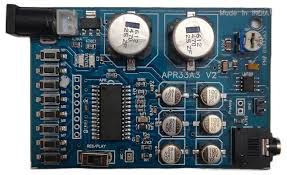
The APR33A3 V2 is a low-power audio playback module designed for embedded systems. It supports various audio formats and is widely used for applications requiring sound effects, voice prompts, or pre-recorded audio playback. The module is compact, easy to integrate, and features a straightforward interface, making it ideal for hobbyists and professionals alike.
Common Applications
- Voice prompts in consumer electronics
- Sound effects in toys and interactive devices
- Audio playback in industrial systems
- Alarm systems with pre-recorded messages
- Educational and DIY projects
The APR33A3 V2 is particularly popular in Arduino-based projects due to its simplicity and compatibility with microcontrollers.
Technical Specifications
The following table outlines the key technical details of the APR33A3 V2 module:
| Parameter | Value |
|---|---|
| Operating Voltage | 3.3V to 5.0V |
| Operating Current | 25mA (typical) |
| Audio Format | ADPCM |
| Playback Duration | Up to 8 minutes (at 8kHz sampling) |
| Sampling Rates Supported | 6kHz, 8kHz, 11kHz, 16kHz |
| Storage | Internal flash memory |
| Control Interface | GPIO or serial |
| Output | Speaker (8Ω, 0.5W) or Line Out |
| Dimensions | 22mm x 15mm x 3mm |
Pin Configuration and Descriptions
The APR33A3 V2 module has a simple pinout for easy integration. Below is the pin configuration:
| Pin | Name | Description |
|---|---|---|
| 1 | VCC | Power supply input (3.3V to 5.0V). |
| 2 | GND | Ground connection. |
| 3 | SP+ | Positive terminal for speaker output. |
| 4 | SP- | Negative terminal for speaker output. |
| 5 | REC | Record control pin. Active HIGH to start recording. |
| 6 | PLAYE | Playback control pin for edge-triggered playback. |
| 7 | PLAYL | Playback control pin for level-triggered playback. |
| 8 | BUSY | Output pin indicating playback status (HIGH = busy, LOW = idle). |
| 9 | MIC+ | Positive terminal for microphone input (for recording). |
| 10 | MIC- | Negative terminal for microphone input (for recording). |
Usage Instructions
How to Use the APR33A3 V2 in a Circuit
Powering the Module:
Connect the VCC pin to a 3.3V or 5.0V power source and the GND pin to ground.Audio Output:
- For speaker output, connect an 8Ω speaker to the SP+ and SP- pins.
- For line-level output, use the appropriate pins (if available on your module version).
Playback Control:
- Use the PLAYE pin for edge-triggered playback. A HIGH pulse will start playback.
- Use the PLAYL pin for level-triggered playback. Hold the pin HIGH to play audio and release to stop.
Recording Audio (if supported):
- Connect a microphone to the MIC+ and MIC- pins.
- Pull the REC pin HIGH to start recording and release it to stop.
Playback Status:
- Monitor the BUSY pin to check playback status. The pin will be HIGH during playback and LOW when idle.
Best Practices
- Use a decoupling capacitor (e.g., 10µF) across the power supply pins to reduce noise.
- Avoid exceeding the voltage and current ratings to prevent damage to the module.
- Use a pull-down resistor on the control pins to ensure stable operation when not actively driven.
- For better audio quality, use a low-noise power supply and shield the microphone input from interference.
Troubleshooting and FAQs
Common Issues and Solutions
No Sound Output
- Cause: Speaker not connected properly or incorrect pin usage.
- Solution: Verify the connections to the SP+ and SP- pins. Ensure the speaker impedance is 8Ω.
Playback Does Not Start
- Cause: Incorrect control pin usage or insufficient voltage.
- Solution: Check the voltage at the VCC pin and ensure the control pins (PLAYE or PLAYL) are triggered correctly.
Distorted Audio
- Cause: Power supply noise or incompatible speaker.
- Solution: Use a decoupling capacitor across the power supply and ensure the speaker matches the module's specifications.
Module Not Responding
- Cause: Faulty wiring or damaged module.
- Solution: Double-check all connections and test the module with a known working setup.
FAQs
Q1: Can I use the APR33A3 V2 with an Arduino?
A1: Yes, the module can be easily controlled using GPIO pins on an Arduino. Example code is provided below.
Q2: How do I record audio on the module?
A2: Connect a microphone to the MIC+ and MIC- pins, then pull the REC pin HIGH to start recording.
Q3: What is the maximum playback duration?
A3: The module supports up to 8 minutes of playback at an 8kHz sampling rate.
Example Arduino Code
Below is an example of how to control the APR33A3 V2 module using an Arduino UNO:
// Define pin connections
#define PLAY_PIN 7  // Pin connected to PLAYE on the module
#define BUSY_PIN 8  // Pin connected to BUSY on the module

void setup() {
  pinMode(PLAY_PIN, OUTPUT); // Set PLAY_PIN as output
  pinMode(BUSY_PIN, INPUT);  // Set BUSY_PIN as input

  digitalWrite(PLAY_PIN, LOW); // Ensure PLAY_PIN is LOW initially
  Serial.begin(9600);         // Initialize serial communication
}

void loop() {
  // Trigger playback
  Serial.println("Playing audio...");
  digitalWrite(PLAY_PIN, HIGH); // Send HIGH pulse to PLAYE pin
  delay(100);                   // Short delay for edge-triggered playback
  digitalWrite(PLAY_PIN, LOW);  // Set PLAY_PIN back to LOW

  // Wait for playback to finish
  while (digitalRead(BUSY_PIN) == HIGH) {
    Serial.println("Audio is playing...");
    delay(500); // Check playback status every 500ms
  }

  Serial.println("Playback finished.");
  delay(5000); // Wait 5 seconds before playing again
}
Code Explanation
- The PLAY_PIN is used to trigger playback via the PLAYE pin on the module.
- The BUSY_PIN monitors the playback status. The Arduino waits until playback is complete before proceeding.
- The code sends a HIGH pulse to the PLAYE pin to start playback.
This documentation provides a comprehensive guide to using the APR33A3 V2 module. Whether you're a beginner or an experienced user, this guide will help you integrate the module into your projects effectively.
Explore Projects Built with APR33A3 V2


Explore Projects Built with APR33A3 V2