
How to Use Charger Micro USB 5V 3A: Examples, Pinouts, and Specs
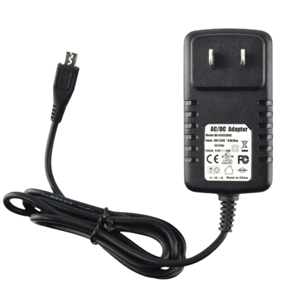
 Design with Charger Micro USB 5V 3A in Cirkit Designer
Introduction
The Charger Micro USB 5V 3A by AC (Manufacturer Part ID: Charger) is a compact and efficient power supply device designed to deliver a stable 5V output with a maximum current of 3A. It features a Micro USB connector, making it ideal for powering and charging a wide range of devices, including smartphones, tablets, single-board computers (e.g., Raspberry Pi), and other portable electronics.
Explore Projects Built with Charger Micro USB 5V 3A
 Open Project in Cirkit Designer
 Open Project in Cirkit Designer
 Open Project in Cirkit Designer
 Open Project in Cirkit Designer
Explore Projects Built with Charger Micro USB 5V 3A
Open Project in Cirkit DesignerOpen Project in Cirkit DesignerOpen Project in Cirkit DesignerOpen Project in Cirkit DesignerCommon Applications and Use Cases
- Charging smartphones, tablets, and other portable devices.
- Powering single-board computers like Raspberry Pi.
- Supplying power to IoT devices and small electronic projects.
- Use in DIY electronics projects requiring a 5V power source.
Technical Specifications
Below are the key technical details of the Charger Micro USB 5V 3A:
| Parameter | Specification |
|---|---|
| Manufacturer | AC |
| Part ID | Charger |
| Output Voltage | 5V DC |
| Maximum Output Current | 3A |
| Connector Type | Micro USB |
| Input Voltage Range | 100-240V AC, 50/60Hz |
| Efficiency | ≥85% |
| Cable Length | Typically 1 meter (varies by model) |
| Operating Temperature | 0°C to 40°C |
| Storage Temperature | -20°C to 70°C |
| Safety Features | Overcurrent, overvoltage, and short-circuit protection |
Pin Configuration and Descriptions
The Micro USB connector used in this charger follows the standard pinout:
| Pin Number | Name | Description |
|---|---|---|
| 1 | VBUS (+5V) | Provides the 5V DC output from the charger. |
| 2 | D- (Data -) | Data line, typically unused for power-only use. |
| 3 | D+ (Data +) | Data line, typically unused for power-only use. |
| 4 | ID | Identification pin, typically unused. |
| 5 | GND (Ground) | Ground connection for the circuit. |
Usage Instructions
How to Use the Charger in a Circuit
- Connect the Charger to a Power Source: Plug the charger into a standard AC outlet (100-240V AC).
- Connect the Micro USB Output: Insert the Micro USB connector into the device or circuit requiring power.
- Verify Compatibility: Ensure the device being powered operates at 5V and does not exceed a current draw of 3A.
- Monitor Operation: Check for proper operation of the connected device. If the device does not power on, verify the connections and ensure the charger is functioning.
Important Considerations and Best Practices
- Avoid Overloading: Do not connect devices that draw more than 3A, as this may cause the charger to overheat or shut down.
- Use Quality Cables: Use high-quality Micro USB cables to minimize voltage drops and ensure reliable power delivery.
- Ventilation: Ensure the charger is used in a well-ventilated area to prevent overheating.
- Check Device Requirements: Confirm that the connected device is compatible with a 5V power supply.
- Avoid Modifications: Do not attempt to modify the charger, as this may void warranties and compromise safety.
Example: Powering an Arduino UNO
The Charger Micro USB 5V 3A can be used to power an Arduino UNO via its USB port. Below is an example of how to connect and use the charger:
- Plug the charger into an AC outlet.
- Connect the Micro USB cable to the charger.
- Use a USB-to-USB-B cable to connect the Arduino UNO to the charger via its USB port.
- The Arduino UNO will power on, and you can upload code or run your project.
Sample Arduino Code
Here is a simple Arduino sketch to blink an LED while powered by the charger:
// This code blinks an LED connected to pin 13 of the Arduino UNO.
// Ensure the Arduino is powered by the Charger Micro USB 5V 3A.

void setup() {
  pinMode(13, OUTPUT); // Set pin 13 as an output pin
}

void loop() {
  digitalWrite(13, HIGH); // Turn the LED on
  delay(1000);            // Wait for 1 second
  digitalWrite(13, LOW);  // Turn the LED off
  delay(1000);            // Wait for 1 second
}
Troubleshooting and FAQs
Common Issues and Solutions
Device Does Not Power On:
- Cause: Loose connection or incompatible device.
- Solution: Check all connections and ensure the device operates at 5V and draws ≤3A.
Charger Overheats:
- Cause: Device connected exceeds the 3A current limit.
- Solution: Disconnect the device and verify its power requirements.
Intermittent Power Delivery:
- Cause: Faulty or low-quality Micro USB cable.
- Solution: Replace the cable with a high-quality one.
No Output Voltage:
- Cause: Charger is damaged or not receiving input power.
- Solution: Verify the AC outlet is functional and inspect the charger for damage.
FAQs
Q1: Can this charger be used with a Raspberry Pi?
A1: Yes, the Charger Micro USB 5V 3A is suitable for powering Raspberry Pi models that require a 5V input and draw ≤3A.
Q2: Is this charger compatible with fast-charging protocols?
A2: No, this charger provides a constant 5V output and does not support fast-charging protocols like Quick Charge or Power Delivery.
Q3: Can I use this charger to power multiple devices simultaneously?
A3: It is not recommended to split the output to power multiple devices, as this may exceed the 3A current limit.
Q4: Is the charger safe to use for long durations?
A4: Yes, the charger is designed for continuous use, provided it is not overloaded and is used in a well-ventilated area.