How to Use motor speed controller: Examples, Pinouts, and Specs
Introduction
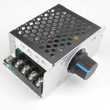
A motor speed controller is an electronic device designed to adjust the speed of an electric motor. It modulates the voltage and/or frequency supplied to the motor, enabling precise control over its rotational speed. These controllers are widely used in applications such as robotics, fans, pumps, and electric vehicles, where speed regulation is crucial for performance and efficiency.
Explore Projects Built with motor speed controller

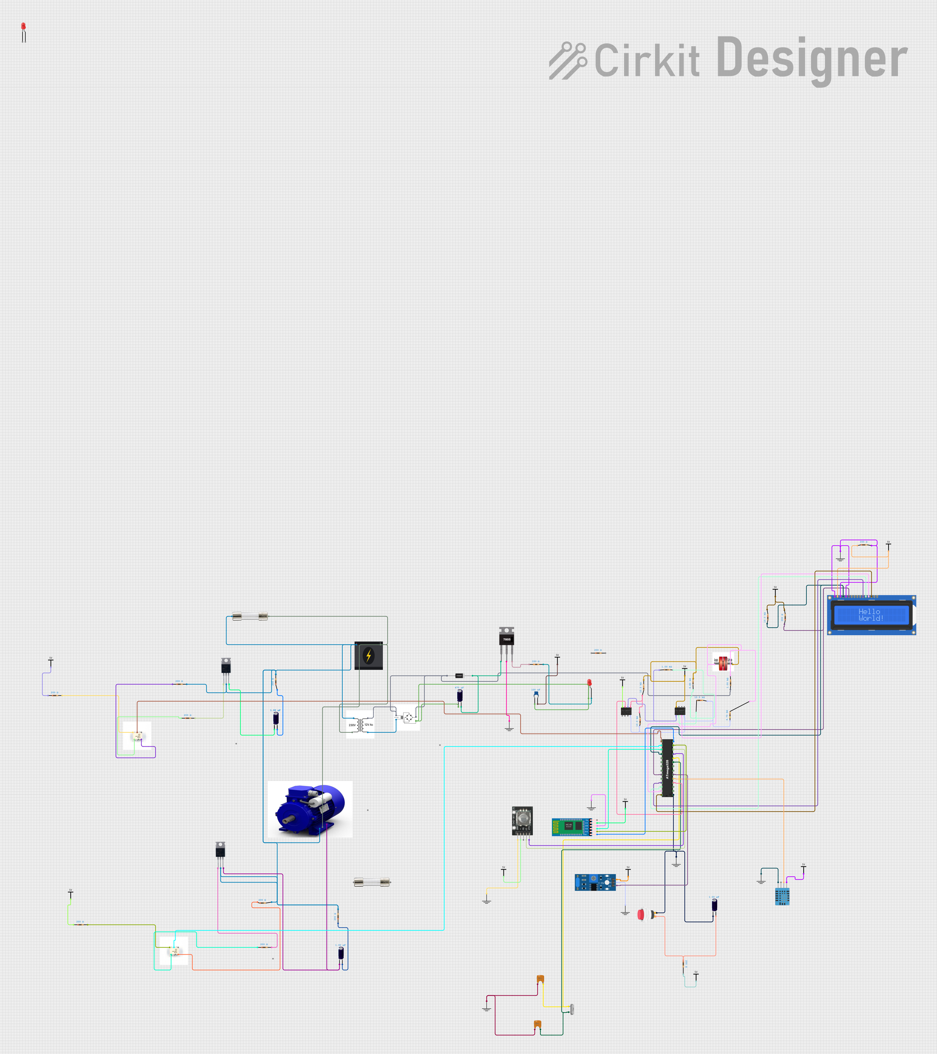
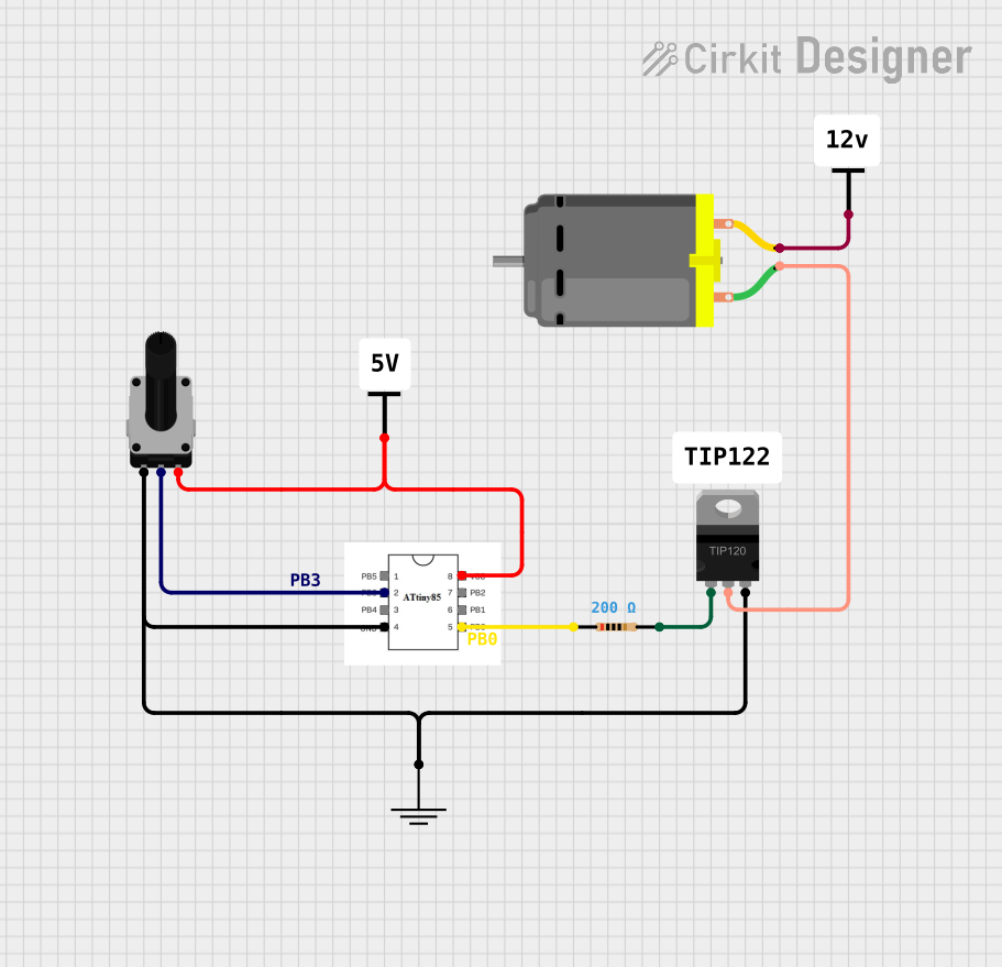
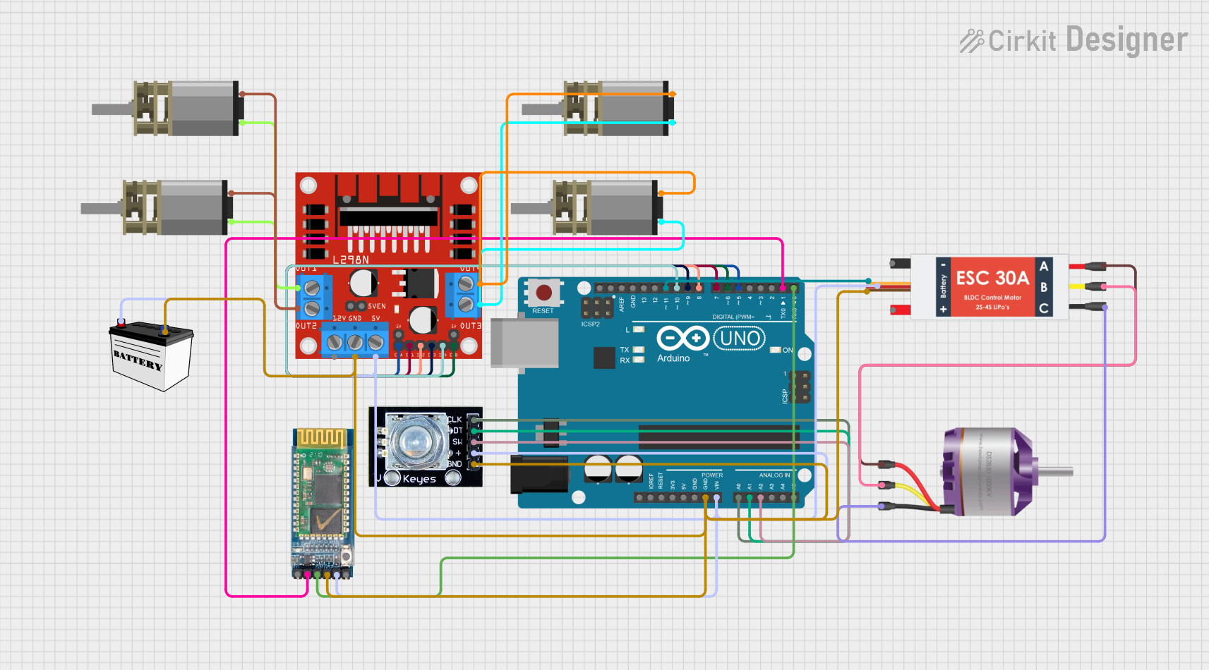
Explore Projects Built with motor speed controller
Technical Specifications
Key Technical Details
- Voltage Range: Typically from 6V to 60V, depending on the model.
- Current Rating: Can vary from a few amps to hundreds of amps.
- Power Rating: Dependent on voltage and current specifications.
- Control Method: PWM (Pulse Width Modulation), analog voltage, or digital signals.
- Frequency Range: Often up to 20kHz for PWM controllers.
Pin Configuration and Descriptions
| Pin Number | Description | Notes |
|---|---|---|
| 1 | Vcc (Input Power) | Connect to positive voltage supply |
| 2 | Ground | Connect to system ground |
| 3 | Control Signal Input | PWM/analog signal input |
| 4 | Motor Output A | Connect to motor terminal |
| 5 | Motor Output B | Connect to motor terminal |
Usage Instructions
Connecting the Motor Speed Controller
- Power Supply Connection: Connect the Vcc pin to a power supply matching the voltage rating of the motor and the controller. Attach the ground pin to the common ground of the system.
- Motor Connection: Connect the motor terminals to the Motor Output A and B pins. Ensure the motor's power requirements do not exceed the controller's ratings.
- Control Signal: Apply a PWM, analog voltage, or digital signal to the Control Signal Input pin to regulate the motor's speed.
Best Practices
- Heat Management: Ensure adequate cooling for the controller, as high currents can generate significant heat.
- Current Limiting: Use a fuse or current limiter to protect against overcurrent conditions.
- Signal Isolation: If using long wires for the control signal, consider using a signal isolator to prevent noise interference.
- Calibration: Calibrate the input signal range to match the controller's specifications for optimal speed control.
Troubleshooting and FAQs
Common Issues
- Motor Not Spinning: Check power supply connections, ensure the control signal is within the specified range, and verify that the motor's requirements do not exceed the controller's limits.
- Erratic Motor Behavior: Inspect for loose connections and signal interference. Ensure PWM frequency is within the controller's acceptable range.
- Overheating: Improve cooling with heatsinks or fans, reduce load on the motor, or check for short circuits.
FAQs
Q: Can I use this controller with any motor type? A: The controller is typically designed for brushed DC motors. Check compatibility with other motor types like brushless DC (BLDC) or stepper motors.
Q: How do I reverse the motor direction? A: Swap the connections between the motor terminals and the Motor Output A and B pins.
Q: What is the maximum frequency for the PWM signal? A: This depends on the specific model of the controller, but it is often up to 20kHz.
Example Arduino Code for PWM Control
// Define the PWM pin connected to the Control Signal Input
const int pwmPin = 3;

// Define the PWM signal range
const int pwmMin = 0;   // Minimum PWM signal (motor off)
const int pwmMax = 255; // Maximum PWM signal (motor at full speed)

void setup() {
  // Set the PWM pin as an output
  pinMode(pwmPin, OUTPUT);
}

void loop() {
  // Increase motor speed gradually
  for (int speed = pwmMin; speed <= pwmMax; speed++) {
    analogWrite(pwmPin, speed);
    delay(10); // Short delay to observe speed change
  }

  // Decrease motor speed gradually
  for (int speed = pwmMax; speed >= pwmMin; speed--) {
    analogWrite(pwmPin, speed);
    delay(10); // Short delay to observe speed change
  }
}
Note: The above code is a simple example of how to control a motor's speed using an Arduino UNO. The analogWrite function sends a PWM signal to the motor speed controller, which in turn controls the motor's speed. Adjust the pwmMin and pwmMax values according to the controller's specifications and the desired speed range.