Cirkit Designer Logo
Cirkit Designer
Your all-in-one circuit design IDE
Home / 
Component Documentation

How to Use TOF10120: Examples, Pinouts, and Specs

Image of TOF10120
Cirkit Designer LogoDesign with TOF10120 in Cirkit Designer

Introduction

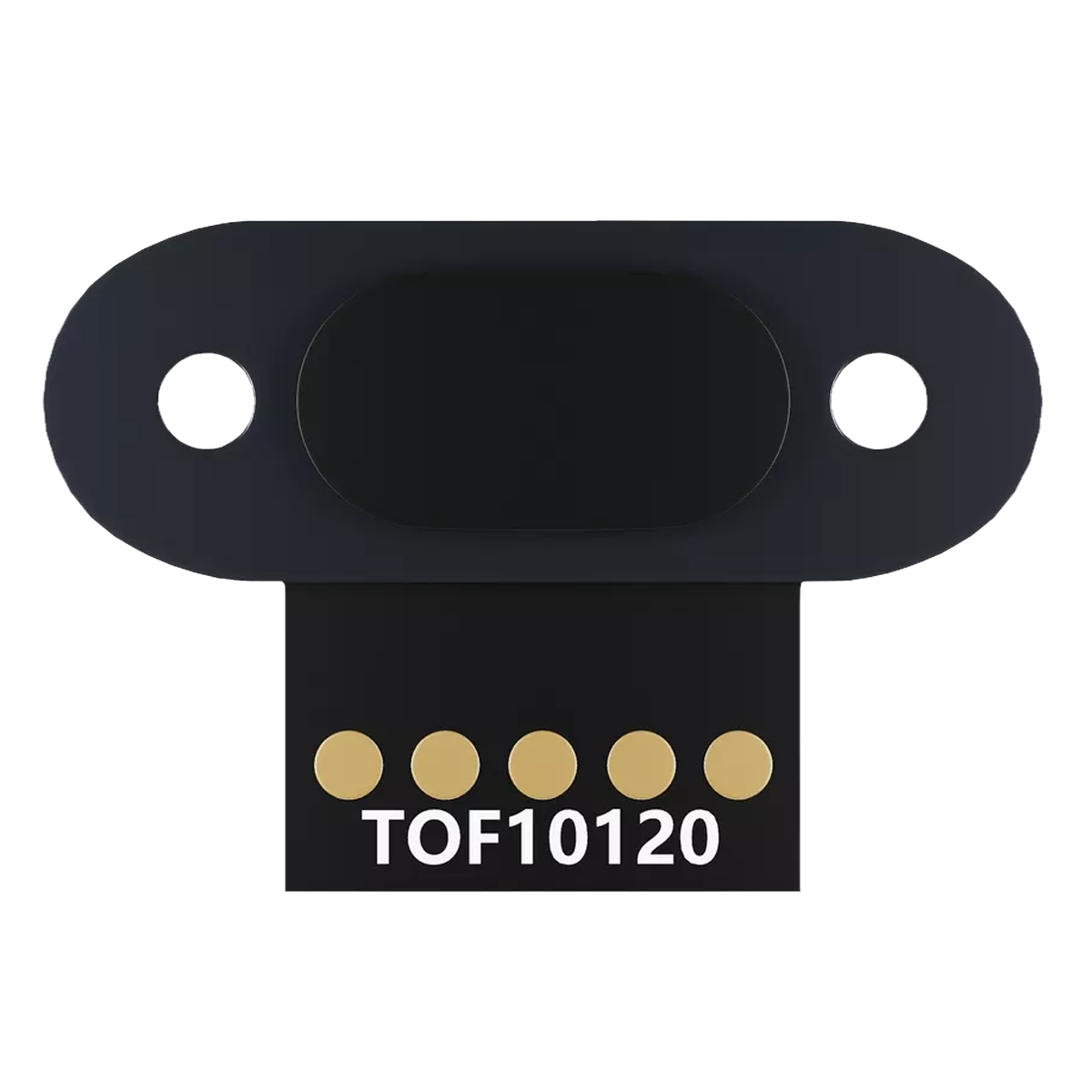
The TOF10120 sensor module is a compact, high-performance Time-of-Flight (ToF) distance sensor that utilizes laser light to accurately measure distances from 10 cm up to 180 cm. The sensor operates on the principle of ToF by emitting a very short infrared light pulse and then measuring the time it takes for the light to bounce back from the object. This technology allows for precise distance measurements, making it ideal for a wide range of applications such as robotics, obstacle avoidance systems, automation, and user presence detection.

Explore Projects Built with TOF10120

Use Cirkit Designer to design, explore, and prototype these projects online. Some projects support real-time simulation. Click "Open Project" to start designing instantly!
Arduino Mega 2560 Based Security System with Fingerprint Authentication and SMS Alerts
Image of Door security system: A project utilizing TOF10120 in a practical application
This circuit features an Arduino Mega 2560 microcontroller interfaced with a SIM800L GSM module, two fingerprint scanners, an I2C LCD display, an IR sensor, and a piezo buzzer. Power management is handled by a PowerBoost 1000 Basic Pad USB, a TP4056 charging module, and a Li-ion 18650 battery, with an option to use a Mini AC-DC 110V-230V to 5V 700mA module for direct power supply. The primary functionality appears to be a security system with GSM communication capabilities, biometric access control, and visual/audible feedback.
Cirkit Designer LogoOpen Project in Cirkit Designer
Battery-Powered Health Monitoring System with Nucleo WB55RG and OLED Display
Image of Pulsefex: A project utilizing TOF10120 in a practical application
This circuit is a multi-sensor data acquisition system that uses a Nucleo WB55RG microcontroller to interface with a digital temperature sensor (TMP102), a pulse oximeter and heart-rate sensor (MAX30102), and a 0.96" OLED display via I2C. Additionally, it includes a Sim800l module for GSM communication, powered by a 3.7V LiPo battery.
Cirkit Designer LogoOpen Project in Cirkit Designer
Solar-Powered IoT Device with ESP32-CAM, SIM900A GSM, and TOF Sensor Integration
Image of mouse trap: A project utilizing TOF10120 in a practical application
This circuit appears to be a solar-powered system with a charge controller connected to a solar panel and a Li-ion battery, managing power distribution. The Arduino UNO microcontroller is interfaced with an ESP32-CAM, SIM900A GSM module, TOF10120 range sensor, MG996R servo, and an I2C LCD screen, likely for monitoring and control purposes. Buck converters are used to regulate voltage for the microcontroller and peripherals, ensuring stable operation.
Cirkit Designer LogoOpen Project in Cirkit Designer
ESP32-Powered Wi-Fi Controlled Robotic Car with OLED Display and Ultrasonic Sensor
Image of playbot: A project utilizing TOF10120 in a practical application
This circuit is a battery-powered system featuring an ESP32 microcontroller that controls an OLED display, a motor driver for two hobby motors, an ultrasonic sensor for distance measurement, and a DFPlayer Mini for audio output through a loudspeaker. The TP4056 module manages battery charging, and a step-up boost converter provides a stable 5V supply to the components.
Cirkit Designer LogoOpen Project in Cirkit Designer

Explore Projects Built with TOF10120

Use Cirkit Designer to design, explore, and prototype these projects online. Some projects support real-time simulation. Click "Open Project" to start designing instantly!
Image of Door security system: A project utilizing TOF10120 in a practical application
Arduino Mega 2560 Based Security System with Fingerprint Authentication and SMS Alerts
This circuit features an Arduino Mega 2560 microcontroller interfaced with a SIM800L GSM module, two fingerprint scanners, an I2C LCD display, an IR sensor, and a piezo buzzer. Power management is handled by a PowerBoost 1000 Basic Pad USB, a TP4056 charging module, and a Li-ion 18650 battery, with an option to use a Mini AC-DC 110V-230V to 5V 700mA module for direct power supply. The primary functionality appears to be a security system with GSM communication capabilities, biometric access control, and visual/audible feedback.
Cirkit Designer LogoOpen Project in Cirkit Designer
Image of Pulsefex: A project utilizing TOF10120 in a practical application
Battery-Powered Health Monitoring System with Nucleo WB55RG and OLED Display
This circuit is a multi-sensor data acquisition system that uses a Nucleo WB55RG microcontroller to interface with a digital temperature sensor (TMP102), a pulse oximeter and heart-rate sensor (MAX30102), and a 0.96" OLED display via I2C. Additionally, it includes a Sim800l module for GSM communication, powered by a 3.7V LiPo battery.
Cirkit Designer LogoOpen Project in Cirkit Designer
Image of mouse trap: A project utilizing TOF10120 in a practical application
Solar-Powered IoT Device with ESP32-CAM, SIM900A GSM, and TOF Sensor Integration
This circuit appears to be a solar-powered system with a charge controller connected to a solar panel and a Li-ion battery, managing power distribution. The Arduino UNO microcontroller is interfaced with an ESP32-CAM, SIM900A GSM module, TOF10120 range sensor, MG996R servo, and an I2C LCD screen, likely for monitoring and control purposes. Buck converters are used to regulate voltage for the microcontroller and peripherals, ensuring stable operation.
Cirkit Designer LogoOpen Project in Cirkit Designer
Image of playbot: A project utilizing TOF10120 in a practical application
ESP32-Powered Wi-Fi Controlled Robotic Car with OLED Display and Ultrasonic Sensor
This circuit is a battery-powered system featuring an ESP32 microcontroller that controls an OLED display, a motor driver for two hobby motors, an ultrasonic sensor for distance measurement, and a DFPlayer Mini for audio output through a loudspeaker. The TP4056 module manages battery charging, and a step-up boost converter provides a stable 5V supply to the components.
Cirkit Designer LogoOpen Project in Cirkit Designer

Common Applications and Use Cases

  • Robotics: obstacle detection and navigation
  • Automation: material level control, object profiling
  • Consumer electronics: gesture recognition, user presence
  • Drones: altitude control, terrain following
  • Smart devices: proximity sensing for power saving

Technical Specifications

Key Technical Details

  • Operating Voltage: 3.3V to 5V
  • Average Current Consumption: 33mA
  • Peak Current Consumption: 40mA
  • Measurement Range: 10cm to 180cm
  • Resolution: 1cm
  • Laser Wavelength: 940nm (invisible and eye-safe)
  • Interface: UART/I2C
  • Operating Temperature: -20°C to 60°C

Pin Configuration and Descriptions

Pin Number Name Description
1 VCC Power supply (3.3V to 5V)
2 GND Ground connection
3 TX UART Transmit (connect to RX of MCU)
4 RX UART Receive (connect to TX of MCU)
5 SCL I2C Clock (optional use)
6 SDA I2C Data (optional use)

Usage Instructions

How to Use the TOF10120 in a Circuit

  1. Power Supply: Connect the VCC pin to a 3.3V or 5V power source and the GND pin to the ground.
  2. Data Communication: For UART communication, connect the TX pin of the TOF10120 to the RX pin of your microcontroller (MCU) and the RX pin to the TX pin of the MCU. For I2C communication, connect the SCL and SDA pins to the corresponding I2C pins on the MCU.
  3. Initialization: Upon power-up, the sensor initializes and starts sending distance measurements at a default baud rate of 115200 bps for UART.

Important Considerations and Best Practices

  • Ensure that the power supply is stable and within the specified voltage range.
  • Avoid exposing the sensor to direct sunlight or strong reflective surfaces, as this may affect accuracy.
  • Keep the sensor lens clean and free from obstructions.
  • For consistent results, calibrate the sensor in the same environmental conditions as it will be used.

Troubleshooting and FAQs

Common Issues

  • Inaccurate Readings: Ensure there are no reflective objects within the field of view and that the sensor is not facing direct sunlight.
  • No Data Output: Check the wiring and connections, ensure the correct baud rate is set for UART communication, and verify that the power supply is within the specified range.

Solutions and Tips

  • Calibration: Perform a calibration procedure if the sensor is giving consistent but incorrect measurements.
  • Interference: If using multiple sensors, ensure they are spaced apart to avoid interference.

FAQs

Q: Can the TOF10120 be used outdoors? A: Yes, but direct sunlight may interfere with the measurements. It is best used in shaded or indoor environments.

Q: What is the maximum baud rate for UART communication? A: The TOF10120 supports a baud rate of up to 115200 bps.

Q: How can I change the I2C address of the sensor? A: The I2C address is fixed and cannot be changed.

Example Code for Arduino UNO

#include <SoftwareSerial.h>

SoftwareSerial TOFSerial(10, 11); // RX, TX

void setup() {
  Serial.begin(9600);
  TOFSerial.begin(115200); // Default baud rate for TOF10120
}

void loop() {
  if (TOFSerial.available()) {
    int distance = TOFSerial.read() << 8;
    distance |= TOFSerial.read(); // Read two bytes to get distance
    Serial.print("Distance: ");
    Serial.print(distance);
    Serial.println(" mm");
  }
}

Note: This example uses the SoftwareSerial library to create a serial connection on pins 10 and 11 of the Arduino UNO. The TOF10120 sends two bytes for each distance measurement, which are combined to form the final distance value in millimeters. Ensure that the TOF10120 is connected with the TX pin to pin 10 and the RX pin to pin 11 on the Arduino UNO.