
How to Use Solution x-606s: Examples, Pinouts, and Specs
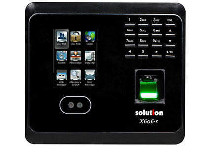
 Design with Solution x-606s in Cirkit Designer
Introduction
The Solution X-606S is a specialized electronic component designed for high-performance applications, particularly in signal processing and communication systems. Known for its exceptional reliability and efficiency, the X-606S is a preferred choice for engineers working on advanced electronic designs. Its robust design and versatile functionality make it suitable for both industrial and commercial use cases.
Explore Projects Built with Solution x-606s
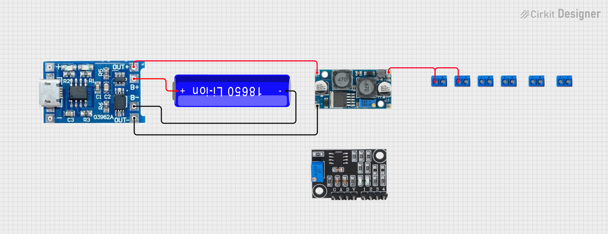 Open Project in Cirkit Designer
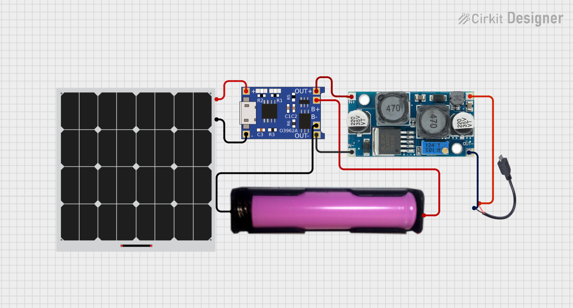 Open Project in Cirkit Designer
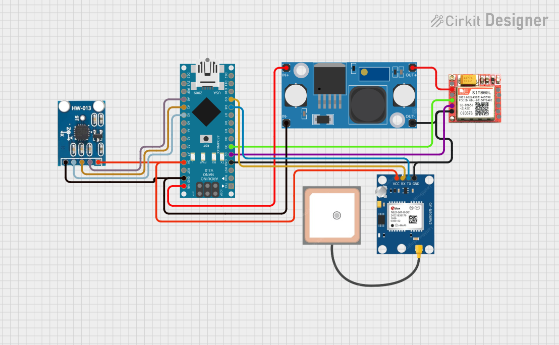 Open Project in Cirkit Designer
 Open Project in Cirkit Designer
Explore Projects Built with Solution x-606s
Open Project in Cirkit DesignerOpen Project in Cirkit DesignerOpen Project in Cirkit DesignerOpen Project in Cirkit DesignerCommon Applications
- Signal processing in communication systems
- High-speed data transmission
- Industrial automation and control systems
- Advanced audio and video processing
- Embedded systems requiring reliable performance
Technical Specifications
Key Technical Details
| Parameter | Value |
|---|---|
| Operating Voltage | 3.3V to 5V |
| Maximum Current | 50 mA |
| Power Consumption | 0.25 W (typical) |
| Operating Temperature | -40°C to +85°C |
| Signal Bandwidth | Up to 2 GHz |
| Package Type | 16-pin QFN |
| Communication Protocol | SPI (Serial Peripheral Interface) |
Pin Configuration and Descriptions
| Pin Number | Pin Name | Description |
|---|---|---|
| 1 | VCC | Power supply input (3.3V to 5V) |
| 2 | GND | Ground connection |
| 3 | MISO | Master In Slave Out (SPI data output) |
| 4 | MOSI | Master Out Slave In (SPI data input) |
| 5 | SCK | Serial Clock (SPI clock input) |
| 6 | CS | Chip Select (active low) |
| 7 | RESET | Reset pin (active low) |
| 8 | INT | Interrupt output |
| 9-16 | NC | Not connected (reserved for future use) |
Usage Instructions
How to Use the Solution X-606S in a Circuit
- Power Supply: Connect the VCC pin to a stable 3.3V or 5V power source and the GND pin to the ground of your circuit.
- SPI Communication: Interface the X-606S with a microcontroller or processor using the SPI protocol. Connect the MISO, MOSI, SCK, and CS pins to the corresponding SPI pins on your microcontroller.
- Reset and Interrupt: Use the RESET pin to initialize the component during startup or in case of a fault. The INT pin can be used to signal events or errors to the microcontroller.
- Bypass Capacitor: Place a 0.1 µF ceramic capacitor close to the VCC pin to filter out noise and ensure stable operation.
Important Considerations and Best Practices
- Ensure that the SPI clock frequency does not exceed the maximum supported by the X-606S (10 MHz).
- Use proper grounding techniques to minimize noise and interference in high-frequency applications.
- Avoid leaving unused pins floating; connect them to GND if not in use.
- Handle the component carefully to prevent damage from electrostatic discharge (ESD).
Example: Connecting the X-606S to an Arduino UNO
Below is an example of how to connect and use the Solution X-606S with an Arduino UNO:
Circuit Connections
| X-606S Pin | Arduino UNO Pin |
|---|---|
| VCC | 5V |
| GND | GND |
| MISO | Pin 12 |
| MOSI | Pin 11 |
| SCK | Pin 13 |
| CS | Pin 10 |
| RESET | Pin 9 |
| INT | Pin 2 |
Arduino Code Example
#include <SPI.h>

// Define pin connections
const int CS_PIN = 10;  // Chip Select pin
const int RESET_PIN = 9; // Reset pin
const int INT_PIN = 2;   // Interrupt pin

void setup() {
  // Initialize serial communication for debugging
  Serial.begin(9600);

  // Configure SPI settings
  SPI.begin();
  pinMode(CS_PIN, OUTPUT);
  pinMode(RESET_PIN, OUTPUT);
  pinMode(INT_PIN, INPUT);

  // Reset the X-606S
  digitalWrite(RESET_PIN, LOW);  // Activate reset
  delay(10);                     // Wait for 10 ms
  digitalWrite(RESET_PIN, HIGH); // Deactivate reset

  Serial.println("X-606S initialized.");
}

void loop() {
  // Example: Send data to the X-606S
  digitalWrite(CS_PIN, LOW);  // Select the X-606S
  SPI.transfer(0x55);         // Send a sample byte (0x55)
  digitalWrite(CS_PIN, HIGH); // Deselect the X-606S

  // Check for interrupt signal
  if (digitalRead(INT_PIN) == HIGH) {
    Serial.println("Interrupt detected!");
  }

  delay(1000); // Wait for 1 second
}
Troubleshooting and FAQs
Common Issues and Solutions
No Response from the X-606S
- Cause: Incorrect SPI connections or configuration.
- Solution: Double-check the wiring and ensure the SPI settings (clock speed, mode) match the X-606S requirements.
Frequent Resets or Unstable Operation
- Cause: Insufficient power supply or noise on the VCC line.
- Solution: Add a bypass capacitor (0.1 µF) near the VCC pin and ensure a stable power source.
Interrupt Pin Not Triggering
- Cause: Incorrect configuration or no events to trigger an interrupt.
- Solution: Verify the INT pin connection and ensure the X-606S is configured to generate interrupts.
Overheating
- Cause: Exceeding the maximum current or voltage ratings.
- Solution: Ensure the operating conditions are within the specified limits.
FAQs
Q: Can the X-606S operate at 3.3V?
A: Yes, the X-606S supports an operating voltage range of 3.3V to 5V.
Q: What is the maximum SPI clock frequency supported?
A: The X-606S supports SPI clock frequencies up to 10 MHz.
Q: Are the NC pins safe to leave unconnected?
A: Yes, the NC (Not Connected) pins can be left unconnected or tied to GND for better stability.
Q: Is the X-606S compatible with 1.8V logic levels?
A: No, the X-606S requires a minimum logic level of 3.3V for proper operation.