How to Use Adafruit RGB Matrix Bonnet for Raspberry Pi: Examples, Pinouts, and Specs
Introduction
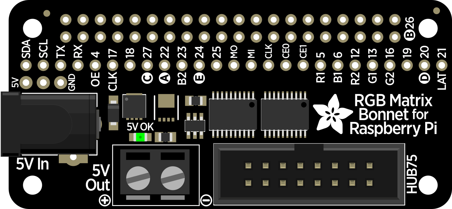
The Adafruit RGB Matrix Bonnet is an add-on accessory for the Raspberry Pi designed to make connecting and controlling RGB LED matrix panels simple and efficient. This bonnet is ideal for creating colorful display outputs for digital signage, gaming, art installations, and other visual projects. With its dedicated driver chip and level shifters, the bonnet ensures high-quality, flicker-free performance.
Explore Projects Built with Adafruit RGB Matrix Bonnet for Raspberry Pi

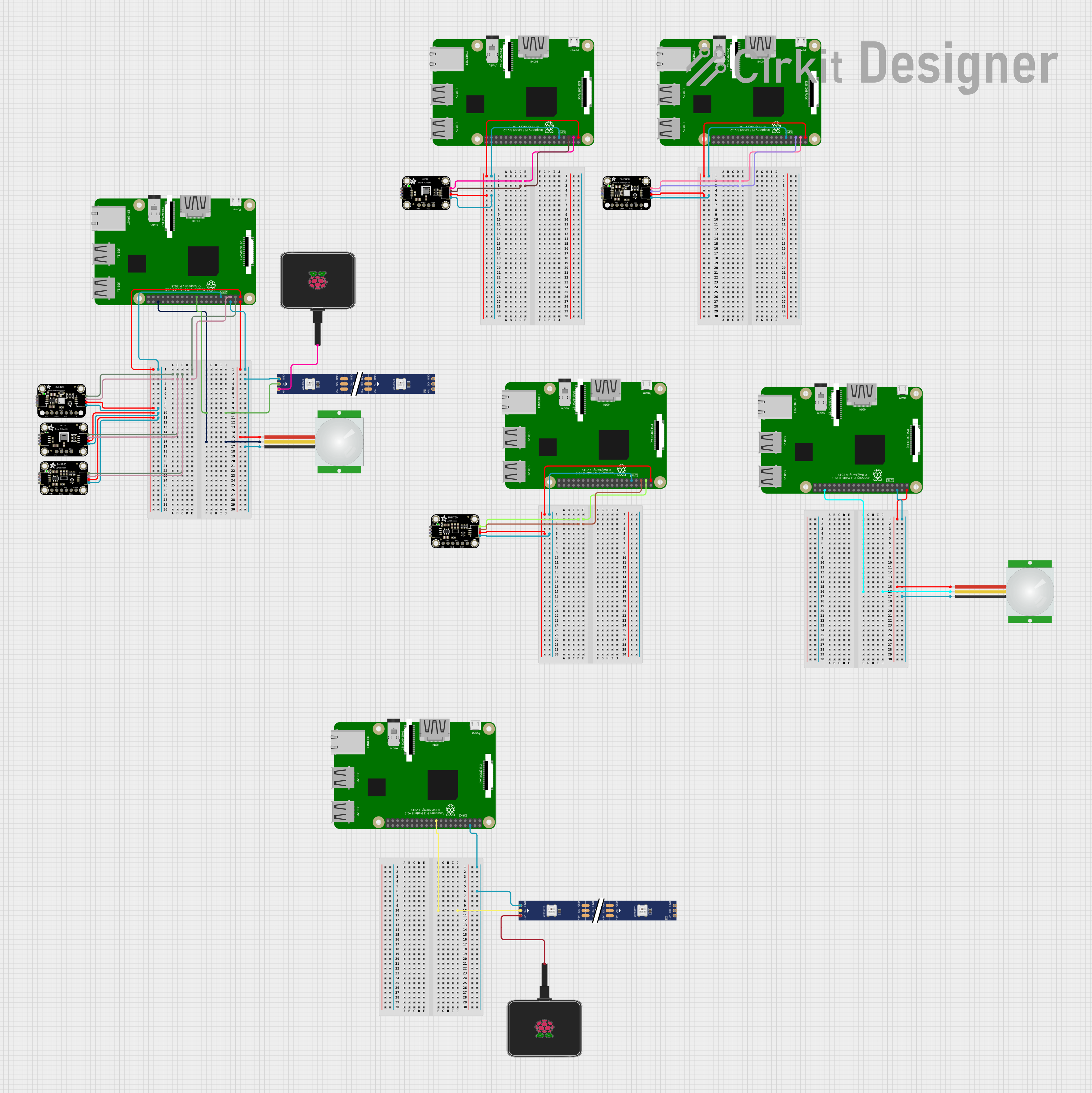
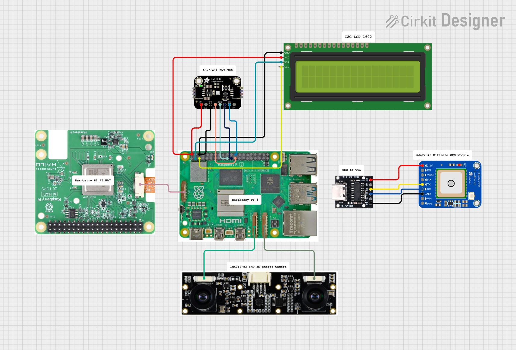

Explore Projects Built with Adafruit RGB Matrix Bonnet for Raspberry Pi
Common Applications and Use Cases
- Digital signage and advertising displays
- Scoreboards and information boards
- Interactive art installations
- Gaming and entertainment systems
- Educational projects and DIY displays
Technical Specifications
Key Technical Details
- Compatibility: Works with Raspberry Pi 2, 3, 4, and Zero models
- Supported Panels: HUB75 type RGB matrices
- Voltage: 5V (supplied by the connected RGB matrix)
- Logic Level Shifting: 3.3V to 5V for interfacing with the Raspberry Pi
Pin Configuration and Descriptions
| Pin Number | Function | Description |
|---|---|---|
| 1 | 5V Power | Powers the Bonnet from the RGB matrix |
| 2 | Ground | Common ground for power and logic |
| 3-8 | RGB Data Lines | Control the color output for the matrix display |
| 9-14 | Address Lines | Select rows on the matrix for scanning |
| 15 | Latch | Latches data into the display on the rising edge |
| 16 | Output Enable | Enables or disables the output to the display |
| 17 | Clock | Clocks data into the display |
Usage Instructions
Connecting the Bonnet to a Raspberry Pi
- Power off your Raspberry Pi.
- Align the GPIO header of the RGB Matrix Bonnet with the GPIO pins on your Raspberry Pi.
- Gently press down to connect the bonnet to the Raspberry Pi ensuring a snug fit.
- Connect the ribbon cable from the RGB LED matrix panel to the bonnet's HUB75 interface.
Software Setup
- Install the Raspberry Pi OS on your Raspberry Pi if you haven't already.
- Connect your Raspberry Pi to the internet and open a terminal window.
- Update your Raspberry Pi's package list and upgrade the existing software:
sudo apt-get update
sudo apt-get upgrade
- Install the RGB Matrix Bonnet software by running the following command:
curl https://raw.githubusercontent.com/adafruit/Raspberry-Pi-Installer-Scripts/master/rgb-matrix.sh | bash
- Follow the on-screen instructions to complete the installation.
Programming the Bonnet
To control the RGB LED matrix, you can use the provided Python library. Here's a simple example that initializes the display and shows a solid color:
from rgbmatrix import RGBMatrix, RGBMatrixOptions
Configuration for the matrix
options = RGBMatrixOptions() options.rows = 32 # Adjust according to your matrix's row count options.cols = 64 # Adjust according to your matrix's column count options.chain_length = 1 options.parallel = 1 options.hardware_mapping = 'adafruit-hat' # If using the Bonnet
matrix = RGBMatrix(options=options)
Creates a red screen
matrix.Fill(255, 0, 0)
Important Considerations and Best Practices
- Always power off the Raspberry Pi before attaching or detaching the bonnet.
- Ensure the ribbon cable is securely connected to the bonnet and the LED matrix.
- Use a 5V power supply capable of providing adequate current for your LED matrix.
- Avoid looking directly at the LEDs when they are powered on, as they can be very bright.
Troubleshooting and FAQs
Common Issues
- Display Not Lighting Up: Check the power supply and connections. Ensure the ribbon cable is properly seated.
- Flickering Display: This may be due to insufficient power. Verify that your power supply meets the requirements.
- Incorrect Colors: Double-check the configuration in your code, specifically the rows, columns, and chain length.
Solutions and Tips for Troubleshooting
- Verify all connections are secure and correct.
- Re-run the installation script to ensure all software components are properly set up.
- Review the example code and compare it with your implementation for any discrepancies.
FAQs
Q: Can I daisy-chain multiple panels together?
A: Yes, the bonnet supports chaining multiple HUB75 panels. Adjust the chain_length option in your code accordingly.
Q: What is the maximum size of the LED matrix I can control with this bonnet? A: The maximum size depends on the Raspberry Pi's processing power and the power supply. Larger displays may require additional considerations for power and signal integrity.
Q: Can I use this bonnet with other programming languages? A: While the provided library is for Python, you can use other languages as long as they can interface with the GPIO pins and meet the timing requirements of the HUB75 protocol.
For further assistance, consult the Adafruit forums or the community resources available online.