How to Use MCP3008 8-channel 10-bit ADC: Examples, Pinouts, and Specs
Introduction
The MCP3008 is a versatile and cost-effective 8-channel 10-bit Analog-to-Digital Converter (ADC) that allows for the conversion of analog signals to digital values with high precision. It is widely used in applications that require multiple analog inputs to be processed by a digital system, such as microcontrollers that do not have enough or any built-in ADCs. Common applications include sensor data reading, data acquisition systems, and any application that requires monitoring of multiple analog sources.
Explore Projects Built with MCP3008 8-channel 10-bit ADC


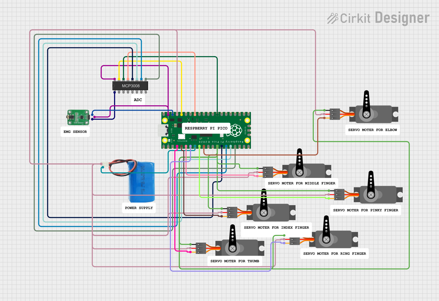
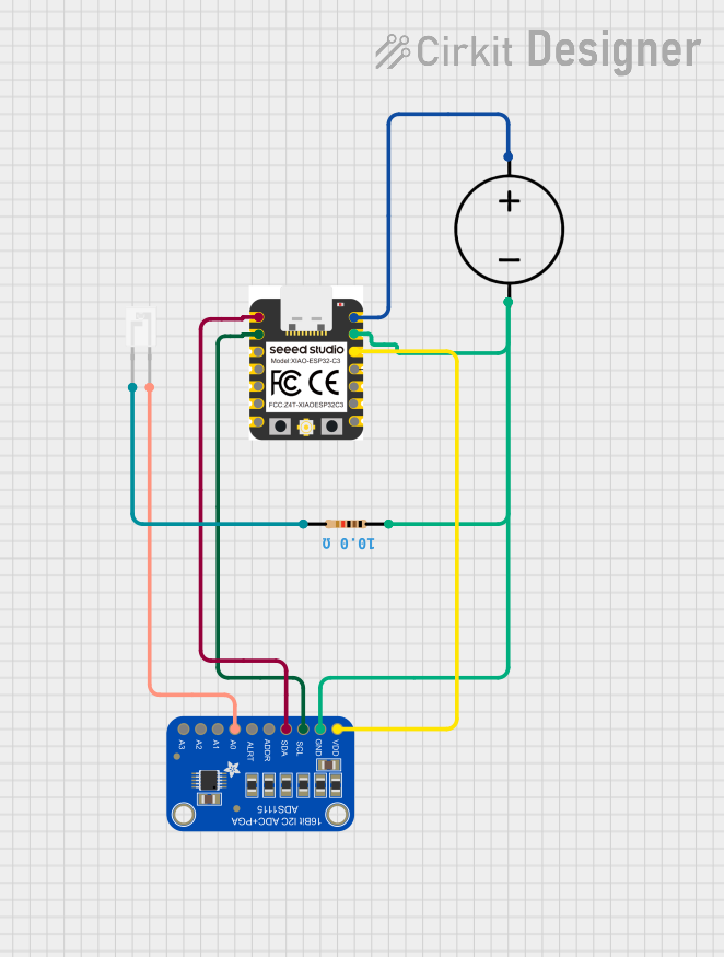
Explore Projects Built with MCP3008 8-channel 10-bit ADC
Technical Specifications
Key Technical Details
- Resolution: 10-bit
- Number of Channels: 8 single-ended or 4 differential inputs
- Analog Input Voltage Range: 0V to VDD
- Digital Interface: SPI-compatible serial interface
- Supply Voltage: 2.7V to 5.5V
- Sampling Rate: Up to 200 ksps (kilo-samples per second)
- Operating Temperature Range: -40°C to +85°C
Pin Configuration and Descriptions
| Pin Number | Name | Description |
|---|---|---|
| 1 | CH0 | Analog input channel 0 |
| 2 | CH1 | Analog input channel 1 |
| 3 | CH2 | Analog input channel 2 |
| 4 | CH3 | Analog input channel 3 |
| 5 | CH4 | Analog input channel 4 |
| 6 | CH5 | Analog input channel 5 |
| 7 | CH6 | Analog input channel 6 |
| 8 | CH7 | Analog input channel 7 |
| 9 | DGND | Digital Ground |
| 10 | CS/SHDN | Chip Select / Shutdown |
| 11 | DIN | SPI Data Input |
| 12 | DOUT | SPI Data Output |
| 13 | CLK | SPI Clock Input |
| 14 | AGND | Analog Ground |
| 15 | VREF | Analog Voltage Reference |
| 16 | VDD | Positive Supply Voltage |
Usage Instructions
How to Use the MCP3008 in a Circuit
Powering the MCP3008:
- Connect VDD to a 2.7V to 5.5V power supply.
- Connect both AGND and DGND to the ground of the power supply.
Connecting Analog Inputs:
- Connect the analog signals to any of the CH0 to CH7 pins.
- Ensure that the analog signal voltage does not exceed the VREF voltage.
Interfacing with a Microcontroller:
- Connect the CLK, DOUT, DIN, and CS/SHDN pins to the corresponding SPI pins on the microcontroller.
Setting the Reference Voltage:
- Connect VREF to the desired reference voltage for the analog inputs, which can be up to VDD.
Important Considerations and Best Practices
- Use a stable and noise-free power supply to minimize reading errors.
- Keep analog signal paths as short as possible to reduce noise pickup.
- Use a decoupling capacitor close to the VDD pin to filter out power supply noise.
- Ensure that the SPI clock speed does not exceed the maximum frequency specified in the datasheet.
Example Code for Arduino UNO
#include <SPI.h>

// MCP3008 SPI commands
const byte START_BIT = 0x01;
const byte SINGLE_ENDED = 0x08;

// SPI settings for MCP3008
SPISettings settings(1350000, MSBFIRST, SPI_MODE0); // SPI clock speed, data order, data mode

// Pin definitions
const int CS_PIN = 10; // Chip Select pin for MCP3008

void setup() {
  Serial.begin(9600);
  SPI.begin();
  pinMode(CS_PIN, OUTPUT);
  digitalWrite(CS_PIN, HIGH); // Deselect the MCP3008
}

int readADC(int channel) {
  byte command = START_BIT | SINGLE_ENDED | (channel << 4);
  digitalWrite(CS_PIN, LOW); // Select the MCP3008
  SPI.beginTransaction(settings);
  SPI.transfer(command); // Start bit and single/differential bit
  byte result1 = SPI.transfer(0x00); // Get the first part of the result
  byte result2 = SPI.transfer(0x00); // Get the second part of the result
  SPI.endTransaction();
  digitalWrite(CS_PIN, HIGH); // Deselect the MCP3008
  int result = ((result1 & 0x03) << 8) | result2; // Combine the two bytes
  return result;
}

void loop() {
  int adcValue = readADC(0); // Read from channel 0
  Serial.print("ADC Value: ");
  Serial.println(adcValue);
  delay(1000);
}
Troubleshooting and FAQs
Common Issues
- Incorrect Readings: Ensure that the analog input voltage does not exceed the reference voltage and that the power supply is stable.
- No Response from MCP3008: Check the wiring, especially the SPI connections and the chip select pin.
- Noisy Signal: Use shorter wires for analog inputs and consider adding a low-pass filter to the input.
Solutions and Tips
- Stabilize Power Supply: Use a decoupling capacitor (0.1 µF ceramic) near the VDD pin.
- Check SPI Settings: Verify that the SPI settings in the code match the MCP3008 specifications.
- Grounding: Ensure that AGND and DGND are connected to a common ground point.
FAQs
Q: Can I use the MCP3008 with a 3.3V system? A: Yes, the MCP3008 can operate at a supply voltage as low as 2.7V.
Q: How can I increase the accuracy of my readings? A: Use a precise reference voltage for VREF, keep analog paths short, and minimize electrical noise.
Q: Can I read differential signals with the MCP3008? A: Yes, the MCP3008 can be configured to read differential signals by appropriately setting the input channel configuration bits.